
User's Manual


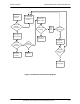
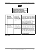


Table Of Contents
- GENERAL MANUAL INFORMATION
- PREPARATION FOR STORAGE OR SHIPMENT
- DESCRIPTION OF EQUIPMENT
- LOCATIONS AND DESCRIPTIONS OF MAJOR COMPONENTS
- EQUIPMENT CHARACTERISTICS
- INSTALLING THE RADIO EQUIPMENT
- INTERCONNECTIONS
- CABLE AND GROUND REQUIREMENTS
- COMPONENT JACK LOCATIONS
- INITIAL PREPARATION FOR USE
- RADIO APPLICATION CODE UPGRADE
- PN SPREADING CODE SELECTION
- ANTENNA AND CABLE INSTALLATION
- CONTROLS AND INDICATORS
- STARTUP AND SHUTDOWN PRODECURES
- OUTPUT POWER SETTINGS
- ANTENNA PLACEMENT
- FUNCTIONAL DESCRIPTION OF EQUIPMENT
- PREVENTIVE MAINTENANCE, INSPECTION, AND CLEANING
- TROUBLESHOOTING
- CORRECTIVE MAINTENANCE
- TEST PROCEDURES
- MDR TESTS
- BDR TESTS
- RADIO DATA PORT TO USER SUPPLIED EQUIPMENT INTERFACE
- PARTS LIST
- BASE DATA RADIO MECHANICAL OUTLINE
- DIAGNOSTIC MENU
- MDR DIAGNOSTIC LCP MENU
- LCP COMMANDS

385700-1006-006 OPERATIONS
Document use is restricted to that described on cover 4-5
The radio communication system at the receiving end receives the packet and passes it to the
vehicle control equipment. The successful receipt of an I frame must be acknowledged by the
receiving RCS and control equipment. This is done by incrementing the Nr field of the control
byte within the next frame sent.
If a vehicle has more than one radio communications system, one of them acts as the main
unit and the others act as auxiliary radios. An MDR responds to a poll only if it is pre-loaded
with a response message by the vehicle control equipment. For vehicles with more than one
MDR, the vehicle control equipment must direct which MDR will be pre-loaded with a
response. Hence, all radio systems in a train receive the message from the region control
equipment but only the main radio system sends the response back.
Additional information about the message protocol can be found in the referenced ICD
document.
4.1.3 MDR/BDR COMMUNICATIONS HANDLING
A communications cycle is the exchange of information between the wayside control
equipment and each vehicle control equipment within the region. During a typical
communications cycle, each vehicle control equipment will be sent a poll request, which will be
acknowledged by a poll response from the vehicle control equipment. Each communications
cycle is followed by the specific command that clears untransmitted messages before
proceeding. The wayside control equipment must query the base data radio every 10 to 20
ms for a poll response, and all poll requests must be sent to the base radio at the beginning of
the communications cycle (within the constraints of the protocol). Mobile radios are polled in
sequence one after the other in a round robin fashion.
The data exchange is based on the High-Level Data Link Control (HDLC) standard protocol to
communicate over the radio channel between the Andrew base and mobile radios. The same
protocol is also used to communicate between base radio and wayside control equipment and
between mobile radio and mobile control equipment over the EIA-530 interface. The
handshaking sequence required by the communications protocol precedes each poll
response.
The referenced Interface Control Document establishes the protocols and interfaces between
wayside and vehicle Control Equipment and Mobile and Base Data Radios.
4.1.4 PN SPREADING CODES
The Direct Sequence Spread Spectrum and CDMA operation of the radios are controlled by
the Pseudo Noise spreading codes contained within the non volatile memory of the radios.
Normal operation of the radios requires (1) that the BDR transmit spreading code equal the
MDR receive spreading code, (2) that that the MDR transmit spreading code equal the BDR
receive spreading code, and (3) that the transmit and receive spreading codes within any
radio be different. The radios are configured with over 80 different spreading codes.
Selection of the codes by the user-supplied equipment is covered in the Radio Communication
System Interface Control Document. Selection of the codes from the LCP terminal is covered
in Chapter 8.