
User's Manual
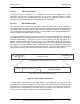


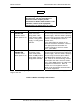


Table Of Contents
- GENERAL MANUAL INFORMATION
- PREPARATION FOR STORAGE OR SHIPMENT
- DESCRIPTION OF EQUIPMENT
- LOCATIONS AND DESCRIPTIONS OF MAJOR COMPONENTS
- EQUIPMENT CHARACTERISTICS
- INSTALLING THE RADIO EQUIPMENT
- INTERCONNECTIONS
- CABLE AND GROUND REQUIREMENTS
- COMPONENT JACK LOCATIONS
- INITIAL PREPARATION FOR USE
- RADIO APPLICATION CODE UPGRADE
- PN SPREADING CODE SELECTION
- ANTENNA AND CABLE INSTALLATION
- CONTROLS AND INDICATORS
- STARTUP AND SHUTDOWN PRODECURES
- OUTPUT POWER SETTINGS
- ANTENNA PLACEMENT
- FUNCTIONAL DESCRIPTION OF EQUIPMENT
- PREVENTIVE MAINTENANCE, INSPECTION, AND CLEANING
- TROUBLESHOOTING
- CORRECTIVE MAINTENANCE
- TEST PROCEDURES
- MDR TESTS
- BDR TESTS
- RADIO DATA PORT TO USER SUPPLIED EQUIPMENT INTERFACE
- PARTS LIST
- BASE DATA RADIO MECHANICAL OUTLINE
- DIAGNOSTIC MENU
- MDR DIAGNOSTIC LCP MENU
- LCP COMMANDS

385700-1006-006 OPERATIONS
Document use is restricted to that described on cover 4-4
4.1.2.3.1 PHYSICAL LAYER
The physical layer is composed of a synchronous serial interface between the control
equipment and the base or mobile transceiver and a radio to radio link based on spread
spectrum technology. The baseband interfaces are based on the EIA-530 interface. The RF
radio link is based on Direct Sequence Spread Spectrum modulation.
4.1.2.3.2 DATALINK LAYER
The data link layer is based on the HDLC (High-level Data Link Control) protocol to
communicate over the radio channel between the base Radio Communication System (RCS)
and mobile RCS. The same protocol is also used to communicate between the RCS and the
control equipment over the EIA-530 interface. A sliding window of one is implemented for the
transfer of HDLC Information Frames (I frames).
The HDLC Information frame (I frame) format is used to transfer data between the base radio
and mobile radio as well as between the radio system and control equipment. The length of a
frame is programmable. Currently is set to 81 bytes (including the two flag bytes). The
wayside control equipment sends an ATC frame to the radio system along with proper RCS
address, control byte and CRC. The first two bytes of the ATC frame will contain the address
of the vehicle. This vehicle address will be used by the radio system to address a mobile radio
on a vehicle. The control byte determines the type of frame. The radio communication system
adds the CRC and flags to the ATC frame and transmits the packet over radio channel.
Figure 4-3 SCP to RCS Frame Format
A mobile radio is addressed by its two byte Address. Two addresses are reserved. A train
address of zero hexadecimal ‘0000’ is not a legal value. The train address hexadecimal ‘FFFF’
is reserved for a broadcast message to all the trains in a region. A broadcast message will
automatically be retransmitted by the BDR until the regional control equipment clears the
frame. A vehicle will send no response to the broadcast message.
Flag
RCS
Address
Control
Byte
Communications-Control System Frame
Maximum 75 bytes
Cyclic
Redundancy
Check
Flag
Train ID Car ID Region ID
Control
Byte
Communications-Control System Data
Maximum 73 B
y
tes
ATC Equipment to Andrew Radio Frame Format
Communications-Control System Frame Format