
User's Manual

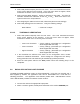

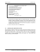
Table Of Contents
- GENERAL MANUAL INFORMATION
- PREPARATION FOR STORAGE OR SHIPMENT
- DESCRIPTION OF EQUIPMENT
- LOCATIONS AND DESCRIPTIONS OF MAJOR COMPONENTS
- EQUIPMENT CHARACTERISTICS
- INSTALLING THE RADIO EQUIPMENT
- INTERCONNECTIONS
- CABLE AND GROUND REQUIREMENTS
- COMPONENT JACK LOCATIONS
- INITIAL PREPARATION FOR USE
- RADIO APPLICATION CODE UPGRADE
- PN SPREADING CODE SELECTION
- ANTENNA AND CABLE INSTALLATION
- CONTROLS AND INDICATORS
- STARTUP AND SHUTDOWN PRODECURES
- OUTPUT POWER SETTINGS
- ANTENNA PLACEMENT
- FUNCTIONAL DESCRIPTION OF EQUIPMENT
- PREVENTIVE MAINTENANCE, INSPECTION, AND CLEANING
- TROUBLESHOOTING
- CORRECTIVE MAINTENANCE
- TEST PROCEDURES
- MDR TESTS
- BDR TESTS
- RADIO DATA PORT TO USER SUPPLIED EQUIPMENT INTERFACE
- PARTS LIST
- BASE DATA RADIO MECHANICAL OUTLINE
- DIAGNOSTIC MENU
- MDR DIAGNOSTIC LCP MENU
- LCP COMMANDS

385700-1006-006 INSTALLATION
Document use is restricted to that described on cover 2-30
RCS Maintenance and Upgrade Menu
[0] Download RCS Software
[1] Download Board Level Test Software
[2] Download Flash Download Software
[3] Download Microwave OS-9 Kernel
[4] Download Power-on Self Test
[5] Download Boot
[6] Run Board Level Test
[7] Run RCS
[8] Run RCS, without an SCP
[9] Display Software Version #’s
[10]Reset Radio
Enter Option [0 - 10]:
7. After the LCP menu appears, select #2 to Set PN Code Index. The user will be
prompted to enter T (transmitter) or R (receiver) to choose which code to set.
Choose T (transmitter) and press <ENTER>. The user is then prompted to select
a number that corresponds to the PN spreading code to be selected. The range of
allowable values is listed on the screen as part of the user prompt. This process is
repeated to set the receiver code.
8. Place the radio power switch to the
OFF
position.
2.8 ANTENNA AND CABLE INSTALLATION
After integrating the MDRs and BDRs into the RCS, ensure that all cabling is securely and
properly attached to each unit. The cable assemblies attached to the individual radio data
ports must be properly shielded. Connect the antenna cable to the radios. Place the MDR
and BDR power switches to the up position (
ON
). Verify that each unit lights its
POWER ON
indicator. Refer to Mobile Data Radio Controls and Indicators, and Base Station Data
Radio Assembly Controls and Indicators.