
User's Manual

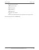
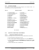

Table Of Contents
- GENERAL MANUAL INFORMATION
- PREPARATION FOR STORAGE OR SHIPMENT
- DESCRIPTION OF EQUIPMENT
- LOCATIONS AND DESCRIPTIONS OF MAJOR COMPONENTS
- EQUIPMENT CHARACTERISTICS
- INSTALLING THE RADIO EQUIPMENT
- INTERCONNECTIONS
- CABLE AND GROUND REQUIREMENTS
- COMPONENT JACK LOCATIONS
- INITIAL PREPARATION FOR USE
- RADIO APPLICATION CODE UPGRADE
- PN SPREADING CODE SELECTION
- ANTENNA AND CABLE INSTALLATION
- CONTROLS AND INDICATORS
- STARTUP AND SHUTDOWN PRODECURES
- OUTPUT POWER SETTINGS
- ANTENNA PLACEMENT
- FUNCTIONAL DESCRIPTION OF EQUIPMENT
- PREVENTIVE MAINTENANCE, INSPECTION, AND CLEANING
- TROUBLESHOOTING
- CORRECTIVE MAINTENANCE
- TEST PROCEDURES
- MDR TESTS
- BDR TESTS
- RADIO DATA PORT TO USER SUPPLIED EQUIPMENT INTERFACE
- PARTS LIST
- BASE DATA RADIO MECHANICAL OUTLINE
- DIAGNOSTIC MENU
- MDR DIAGNOSTIC LCP MENU
- LCP COMMANDS

385700-1006-006 INSTALLATION
Document use is restricted to that described on cover 2-29
one is included with the radio.
13. From the RCS Maintenance and Upgrade menu, select option 8 (by pressing ‘8’
and then <ENTER>) to run the RCS application software without an SCP
connected. Verify that the appropriate LCP Menu Screen appears on the LCP
terminal.
14. Place the radio power switch to the
OFF
position.
2.7 PN SPREADING CODE SELECTION
In order for a BDR to communicate with and MDR, and vice versa, the spreading codes of the
radio must be set to the correct values. The user during system configuration determines the
initial spreading code selected. The spreading code is changed dynamically during operation
based on the user’s system design.
The process to select the spreading code via the LCP menu is given below.
1. Connect the radio to the appropriate input power.
2. Attach a 2 watt or greater, 20 dB power attenuator to the radio’s
ANTENNA
port.
3. Connect cabling between the radio
DIAGNOSTIC
port and dumb terminal, an IBM
PC with Procomm™ Software, or any communications software that supports
VT100 emulation.
4. Place the radio power switch to the
ON
position.
5. Upon completion of the self-test, the LCP terminal will appear as shown below.
**** Starting RCS Self Test... ****
68302 RAM Test: PASSED or FAILED
FLASH TEST: PASSED or FAILED
ATMEL AT59C11 EEPROM Test: PASSED or FAILED
68302 SCC1 Internal Loopback Test: PASSED or FAILED
68302 SCC2 Internal Loopback Test: PASSED or FAILED
68302 SCC3 Internal Loopback Test: PASSED or FAILED
DUART 68681 Local Loopback Test: PASSED or FAILED
**** RCS Self Test Complete ****
Automatically running RCS ... Press 3 <CRs> to abort.
6. Press the <ENTER> key 3 times. This should bring up the RCS Maintenance and
Upgrade menu. Select option 8 (by pressing ‘8’ and then <ENTER>) to run the
RCS application software without an SCP connected. Verify that the appropriate
LCP Menu Screen appears on the LCP terminal.