
User's Manual

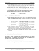

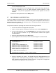
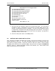
Table Of Contents
- GENERAL MANUAL INFORMATION
- PREPARATION FOR STORAGE OR SHIPMENT
- DESCRIPTION OF EQUIPMENT
- LOCATIONS AND DESCRIPTIONS OF MAJOR COMPONENTS
- EQUIPMENT CHARACTERISTICS
- INSTALLING THE RADIO EQUIPMENT
- INTERCONNECTIONS
- CABLE AND GROUND REQUIREMENTS
- COMPONENT JACK LOCATIONS
- INITIAL PREPARATION FOR USE
- RADIO APPLICATION CODE UPGRADE
- PN SPREADING CODE SELECTION
- ANTENNA AND CABLE INSTALLATION
- CONTROLS AND INDICATORS
- STARTUP AND SHUTDOWN PRODECURES
- OUTPUT POWER SETTINGS
- ANTENNA PLACEMENT
- FUNCTIONAL DESCRIPTION OF EQUIPMENT
- PREVENTIVE MAINTENANCE, INSPECTION, AND CLEANING
- TROUBLESHOOTING
- CORRECTIVE MAINTENANCE
- TEST PROCEDURES
- MDR TESTS
- BDR TESTS
- RADIO DATA PORT TO USER SUPPLIED EQUIPMENT INTERFACE
- PARTS LIST
- BASE DATA RADIO MECHANICAL OUTLINE
- DIAGNOSTIC MENU
- MDR DIAGNOSTIC LCP MENU
- LCP COMMANDS

385700-1006-006 INSTALLATION
Document use is restricted to that described on cover 2-27
5. Select #28 (Status Request) from the LCP menu. The Local Command Processor
(LCP) screen appears on the terminal. If the LCP menu does not appear, follow
instructions in Section 1.4.1 to correctly set the terminal.
6. Select #24 (Set RCS Address). Assign an address for that radio. The range of
allowable hexadecimal addresses is from 01
16
to FE
16
. Each base radio in the
system must have a unique address.
7. After assigning the address for that radio, select #36 (Save Current Settings).
8. Select #35 (Setting) from the LCP menu. Verify the following settings:
RCS Address = “Value set in step 6”
2.5.6.2 THRESHOLD VERIFICATION
1. Select #28 (Status Request) from the LCP menu. The Local Command Processor
(LCP) screen appears on the terminal. If the LCP menu does not appear, follow
instruction in Section 2.5.1 to correctly set the terminal.
• Lower Lock Threshold = factory settings, (thresholds per configuration
sheet shipped with the radio)
• Lower Threshold = factory settings, (thresholds per configuration
sheet shipped with the radio)
• Upper Threshold = factory settings, (thresholds per configuration
sheet shipped with the radio)
2. If the thresholds are different from those on the configuration sheet, contact
Andrew for additional information. These settings are configured at the factory
during production test and should only be modified by qualified personnel.
3. Place the radio power switch to the
OFF
position unless the following step is to be
completed.
2.6 RADIO APPLICATION CODE UPGRADE
The BDR and MDR application codes are field upgradeable. Using the LCP terminal and a
disk supplied by Andrew, the application code can be downloaded into a radio with the
following procedure. The application code diskette (mobile radio = 385700-5002 or base
radio =385700-5003) includes the software version number.
1. Connect the radio to the appropriate input power.
2. Attach a 2 watt or greater, 20 dB power attenuator to the radio’s
ANTENNA
port.