
User's Manual

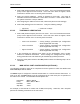

Table Of Contents
- GENERAL MANUAL INFORMATION
- PREPARATION FOR STORAGE OR SHIPMENT
- DESCRIPTION OF EQUIPMENT
- LOCATIONS AND DESCRIPTIONS OF MAJOR COMPONENTS
- EQUIPMENT CHARACTERISTICS
- INSTALLING THE RADIO EQUIPMENT
- INTERCONNECTIONS
- CABLE AND GROUND REQUIREMENTS
- COMPONENT JACK LOCATIONS
- INITIAL PREPARATION FOR USE
- RADIO APPLICATION CODE UPGRADE
- PN SPREADING CODE SELECTION
- ANTENNA AND CABLE INSTALLATION
- CONTROLS AND INDICATORS
- STARTUP AND SHUTDOWN PRODECURES
- OUTPUT POWER SETTINGS
- ANTENNA PLACEMENT
- FUNCTIONAL DESCRIPTION OF EQUIPMENT
- PREVENTIVE MAINTENANCE, INSPECTION, AND CLEANING
- TROUBLESHOOTING
- CORRECTIVE MAINTENANCE
- TEST PROCEDURES
- MDR TESTS
- BDR TESTS
- RADIO DATA PORT TO USER SUPPLIED EQUIPMENT INTERFACE
- PARTS LIST
- BASE DATA RADIO MECHANICAL OUTLINE
- DIAGNOSTIC MENU
- MDR DIAGNOSTIC LCP MENU
- LCP COMMANDS

385700-1006-006 INSTALLATION
Document use is restricted to that described on cover 2-23
2.5.3 VEHICLE LCP MENU
The following is a typical command menu that will appear on the computer monitor. The
menu allows the user to manually operate the MDR.
Phase II Vehicle LCP Menu SW Ver #: xxxx
1. Vehicle Address (Train ID) 21. A/D Select
2. Set PN Index (CDMA Code) 22. Set Clock Search
3. Program Synthesizers 23. OS-9 Shell
4. Reserved 24. Set RCS Address
5. Reset DSP 25. Reserved
6. Reserved 26. SSR Status Request
7. Reset PN 27. System Block Status
8. Reset PN (RX, STROBE) 28. Status Request
9. Reserved 29. Show Poll Counters
10. Set Upper Threshold 30. Clear Poll Counters
11. Upper Thres w/o PN Reset 31. RS-232 Parameters
12. Set Lower Threshold 32. Read TRACK/AGC Values
13. Lower Thres w/o PN Reset 33. Set dBm Output Level
14. Set Lower Lock Threshold 34. Change dBm/DAC Values
15. Disable Transmitter 35. Serial EEPROM Display
16. Enable Transmitter 36. Save Current Settings
17. Load SC Register 37. Load Tnd SC Register
18. Disable Test Port 38. Reserved
19. Enable Test Port 39. Reserved
20. PN Test Select 40. Display System Log
Enter Selection
2.5.4 MDR INITIAL OPERATIONAL ADJUSTMENTS
2.5.4.1 UNIQUE ADDRESS QUALIFIER
Perform the following procedures only when first receiving an MDR from the manufacturer.
1. Connect the MDR to the appropriate DC power.
2. Attach a 2 watt or greater, 20 dB power attenuator to the radio’s
ANTENNA
port.
3. Connect cabling between the radio
DIAGNOSTIC
port and dumb terminal, an IBM
PC with Procomm™ Software, or any communications software that supports
VT100 emulation.
4. Place the radio power switch to the
ON
position.