
User's Manual

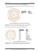
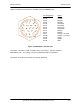

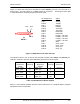
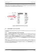
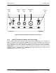
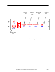
Table Of Contents
- GENERAL MANUAL INFORMATION
- PREPARATION FOR STORAGE OR SHIPMENT
- DESCRIPTION OF EQUIPMENT
- LOCATIONS AND DESCRIPTIONS OF MAJOR COMPONENTS
- EQUIPMENT CHARACTERISTICS
- INSTALLING THE RADIO EQUIPMENT
- INTERCONNECTIONS
- CABLE AND GROUND REQUIREMENTS
- COMPONENT JACK LOCATIONS
- INITIAL PREPARATION FOR USE
- RADIO APPLICATION CODE UPGRADE
- PN SPREADING CODE SELECTION
- ANTENNA AND CABLE INSTALLATION
- CONTROLS AND INDICATORS
- STARTUP AND SHUTDOWN PRODECURES
- OUTPUT POWER SETTINGS
- ANTENNA PLACEMENT
- FUNCTIONAL DESCRIPTION OF EQUIPMENT
- PREVENTIVE MAINTENANCE, INSPECTION, AND CLEANING
- TROUBLESHOOTING
- CORRECTIVE MAINTENANCE
- TEST PROCEDURES
- MDR TESTS
- BDR TESTS
- RADIO DATA PORT TO USER SUPPLIED EQUIPMENT INTERFACE
- PARTS LIST
- BASE DATA RADIO MECHANICAL OUTLINE
- DIAGNOSTIC MENU
- MDR DIAGNOSTIC LCP MENU
- LCP COMMANDS

385700-1006-006 INSTALLATION
Document use is restricted to that described on cover 2-17
Figure 2-8 shows the connector of the BDR rear panel DATA 2 port (J3). The connector is a
25 pin D-sub. The part number is ITT DBU-25S-FO or equivalent. A mating connector with a
metal backshell for shielding purposes should be used.
Figure 2-8 BDR Data 2 Port Cable Pin-outs
2.4 COMPONENT JACK LOCATIONS
The following paragraphs describe the purpose and location of the jacks for each of the radio
assemblies.
2.4.1 MOBILE DATA RADIO JACK LOCATIONS
Figure 2-9 depicts the MDR connector panel. The MDR front panel contains two data jacks
,
DATA 1
(J2) and
DATA 2
(J3). The MDR transmits and receives data from the control
equipment across the
DATA 1
port (J2). A cable connects the
ANTENNA
port (J5) to the
antenna. A cable connects the
DIAGNOSTIC
port (J4) to an LCP terminal providing a menu-
driven user interface (refer to paragraph 2.5.2). Port
POWER IN
(J1) connects the MDR to
the VDC power source.
DATA 2
port is an RS-232 port that can be connected to customer provided equipment as
required.
DATA 2
provides asynchronous data that is sent from the BDR. The parameters of
this port are programmable via the diagnostic terminal. The
DIAGNOSTIC
port is
unconnected during normal operation.
Pin Assignment Signal
PIN 2 TXD(A)
PIN 14 TXD(B)
PIN 3 RXD(A)
PIN 16 RXD(B)
PIN 15 TXCLK(A)
PIN 12 TXCLK(B)
PIN 17 RXCLK(A)
PIN 9 RXCLK(B)
PIN 4 RTS(A)
PIN 19 RTS(B)
PIN 5 CTS(A)
PIN 13 CTS(B)
PIN 7 GND
J3
DATA 2
Pin 1
Pin 2
PIN 14