
User's Manual


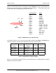
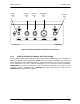
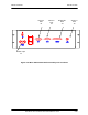
Table Of Contents
- GENERAL MANUAL INFORMATION
- PREPARATION FOR STORAGE OR SHIPMENT
- DESCRIPTION OF EQUIPMENT
- LOCATIONS AND DESCRIPTIONS OF MAJOR COMPONENTS
- EQUIPMENT CHARACTERISTICS
- INSTALLING THE RADIO EQUIPMENT
- INTERCONNECTIONS
- CABLE AND GROUND REQUIREMENTS
- COMPONENT JACK LOCATIONS
- INITIAL PREPARATION FOR USE
- RADIO APPLICATION CODE UPGRADE
- PN SPREADING CODE SELECTION
- ANTENNA AND CABLE INSTALLATION
- CONTROLS AND INDICATORS
- STARTUP AND SHUTDOWN PRODECURES
- OUTPUT POWER SETTINGS
- ANTENNA PLACEMENT
- FUNCTIONAL DESCRIPTION OF EQUIPMENT
- PREVENTIVE MAINTENANCE, INSPECTION, AND CLEANING
- TROUBLESHOOTING
- CORRECTIVE MAINTENANCE
- TEST PROCEDURES
- MDR TESTS
- BDR TESTS
- RADIO DATA PORT TO USER SUPPLIED EQUIPMENT INTERFACE
- PARTS LIST
- BASE DATA RADIO MECHANICAL OUTLINE
- DIAGNOSTIC MENU
- MDR DIAGNOSTIC LCP MENU
- LCP COMMANDS

385700-1006-006 INSTALLATION
Document use is restricted to that described on cover 2-12
2.3.1 CONNECTOR PIN-OUTS
Refer to Figures 2-2 through Figure 2-8 for the connector pin-out information for the MDR and
BDR ports. Unlisted pins are no connects or reserved. Refer to attached cable assembly
drawing package for typical external cable details.
Figure 2-2 shows the connector for the MDR front
POWER IN
connector.
The
Power IN
connector is a MIL-C_26482, Series 1 connector. The part number is
MS3114E8-3P or equivalent. The mating connector is MS3116F8-3S or equivalent.
Figure 2-2 MDR Input DC Power Pin-outs
C
A
B
Pin Assignment Signal
PIN A DC(+)
PIN B Ground
PIN C Ground