
User's Manual

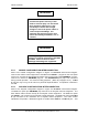
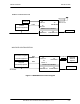
Table Of Contents
- GENERAL MANUAL INFORMATION
- PREPARATION FOR STORAGE OR SHIPMENT
- DESCRIPTION OF EQUIPMENT
- LOCATIONS AND DESCRIPTIONS OF MAJOR COMPONENTS
- EQUIPMENT CHARACTERISTICS
- INSTALLING THE RADIO EQUIPMENT
- INTERCONNECTIONS
- CABLE AND GROUND REQUIREMENTS
- COMPONENT JACK LOCATIONS
- INITIAL PREPARATION FOR USE
- RADIO APPLICATION CODE UPGRADE
- PN SPREADING CODE SELECTION
- ANTENNA AND CABLE INSTALLATION
- CONTROLS AND INDICATORS
- STARTUP AND SHUTDOWN PRODECURES
- OUTPUT POWER SETTINGS
- ANTENNA PLACEMENT
- FUNCTIONAL DESCRIPTION OF EQUIPMENT
- PREVENTIVE MAINTENANCE, INSPECTION, AND CLEANING
- TROUBLESHOOTING
- CORRECTIVE MAINTENANCE
- TEST PROCEDURES
- MDR TESTS
- BDR TESTS
- RADIO DATA PORT TO USER SUPPLIED EQUIPMENT INTERFACE
- PARTS LIST
- BASE DATA RADIO MECHANICAL OUTLINE
- DIAGNOSTIC MENU
- MDR DIAGNOSTIC LCP MENU
- LCP COMMANDS

385700-1006-006 INSTALLATION
Document use is restricted to that described on cover 2-9
The antenna is an electrical conductor.
Contact with power lines may cause
death or serious injury. Do not install
these antennas where there is any
possibility of contact with or high
voltage arc-over from power cables or
service drops to buildings. The
antennas and mast must not be near
power lines during installation, use, or
removal.
Before applying power, verify that the
antenna is securely connected to the MDR
and BDR. Failure to observe these
warnings will damage the equipment.
2.2.1 MOBILE CONFIGURATION INTERCONNECTION
Refer to the mobile configuration diagram in Figure 2-1 MDR/BDR Interconnect Diagram.
Connect the vehicle control equipment to the MDR at the
DATA 1
(J2) port on the front panel
of the unit. Connect the appropriate DC power source to the front panel
POWER IN
(J1) port.
Connect an antenna to
ANTENNA
(J5) port. The
DIAGNOSTIC
port (J4) is not connected
during normal operation. It is used for testing purposes. (Refer to paragraph 2.5.2.) .
DATA
2
(J3) port may or may not be used in a particular implementation. Its operation is defined in
the ICD.
2.2.2 WAYSIDE CONFIGURATION INTERCONNECTION
Refer to the wayside configuration diagram in Figure 2-1 MDR/BDR Interconnect Diagram.
The BDR rear panel port
ANTENNA
(J5) connects to the wayside antenna subsystem. The
base station radios connect directly to the wayside control equipment. The BDR rear panel
port
DATA 1
(J2) connects to the wayside control equipment. The BDR rear panel port
DATA
2
(J3) connects to the redundant set of wayside control equipment. The active control
equipment will provide a differential signal to enable either
DATA 1
or
DATA 2
port. This
WARNING
WARNING