
User's Manual

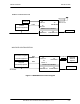
Table Of Contents
- GENERAL MANUAL INFORMATION
- PREPARATION FOR STORAGE OR SHIPMENT
- DESCRIPTION OF EQUIPMENT
- LOCATIONS AND DESCRIPTIONS OF MAJOR COMPONENTS
- EQUIPMENT CHARACTERISTICS
- INSTALLING THE RADIO EQUIPMENT
- INTERCONNECTIONS
- CABLE AND GROUND REQUIREMENTS
- COMPONENT JACK LOCATIONS
- INITIAL PREPARATION FOR USE
- RADIO APPLICATION CODE UPGRADE
- PN SPREADING CODE SELECTION
- ANTENNA AND CABLE INSTALLATION
- CONTROLS AND INDICATORS
- STARTUP AND SHUTDOWN PRODECURES
- OUTPUT POWER SETTINGS
- ANTENNA PLACEMENT
- FUNCTIONAL DESCRIPTION OF EQUIPMENT
- PREVENTIVE MAINTENANCE, INSPECTION, AND CLEANING
- TROUBLESHOOTING
- CORRECTIVE MAINTENANCE
- TEST PROCEDURES
- MDR TESTS
- BDR TESTS
- RADIO DATA PORT TO USER SUPPLIED EQUIPMENT INTERFACE
- PARTS LIST
- BASE DATA RADIO MECHANICAL OUTLINE
- DIAGNOSTIC MENU
- MDR DIAGNOSTIC LCP MENU
- LCP COMMANDS

385700-1006-006 INSTALLATION
Document use is restricted to that described on cover 2-8
CHAPTER 2
INSTALLATION
2.1 INSTALLING THE RADIO EQUIPMENT
This chapter provides information to install the base and mobile data radios (MDR and BDR)
and related equipment and to prepare the equipment for use.
2.1.1 UNPACKING AND INSPECTION
Unpacking the mobile and base station data radios does not require special procedures. Use
normal shop procedures to unpack the equipment.
Carefully inspect the shipping containers and equipment. If the containers show damage,
inspect the equipment in those containers with extra care. Do not open containers with
extreme damage.
Check equipment for bent frames, protrusions, and dents. Pay close attention to external
brackets, controls and connectors, because they are especially susceptible to damage during
shipment.
If you find damage to the equipment, notify Andrew Corporation’s at
• 1-800-854-7732 (Inside the USA)
• 972-235-1222 (Outside the USA)
2.1.2 PROPER INSTALLATION OF UNITS
The MDR is designed to be attached to a mounting plate or bracket using standard 3/8”
hardware. Connect the MDR to the appropriate DC power source and antenna. The operator
is responsible for insuring that the selected antennas and radio are operated in compliance
with FCC Part 15 regulations.
The typical BDR is installed in standard 19” equipment racks. It can also be mounted on a
wall in a stand-alone configuration. Optionally, the BDR can be configured to be mounted on
poles, similar to a MDR.
2.2 INTERCONNECTIONS
Refer to Figure 2-1 MDR/BDR Interconnect Diagram, for a block diagram of wiring runs and
connector designations. The following paragraphs describe the interconnections directly
related to the mobile data and base station radios.