
User's Manual
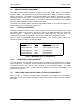

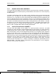
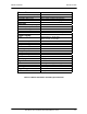
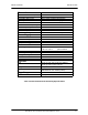
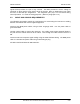
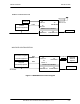
Table Of Contents
- GENERAL MANUAL INFORMATION
- PREPARATION FOR STORAGE OR SHIPMENT
- DESCRIPTION OF EQUIPMENT
- LOCATIONS AND DESCRIPTIONS OF MAJOR COMPONENTS
- EQUIPMENT CHARACTERISTICS
- INSTALLING THE RADIO EQUIPMENT
- INTERCONNECTIONS
- CABLE AND GROUND REQUIREMENTS
- COMPONENT JACK LOCATIONS
- INITIAL PREPARATION FOR USE
- RADIO APPLICATION CODE UPGRADE
- PN SPREADING CODE SELECTION
- ANTENNA AND CABLE INSTALLATION
- CONTROLS AND INDICATORS
- STARTUP AND SHUTDOWN PRODECURES
- OUTPUT POWER SETTINGS
- ANTENNA PLACEMENT
- FUNCTIONAL DESCRIPTION OF EQUIPMENT
- PREVENTIVE MAINTENANCE, INSPECTION, AND CLEANING
- TROUBLESHOOTING
- CORRECTIVE MAINTENANCE
- TEST PROCEDURES
- MDR TESTS
- BDR TESTS
- RADIO DATA PORT TO USER SUPPLIED EQUIPMENT INTERFACE
- PARTS LIST
- BASE DATA RADIO MECHANICAL OUTLINE
- DIAGNOSTIC MENU
- MDR DIAGNOSTIC LCP MENU
- LCP COMMANDS

385700-1006-006 INSTALLATION
Document use is restricted to that described on cover 1-4
1.4.1 MOBILE DATA RADIO ASSEMBLY
The mobile data radio (MDR) uses direct sequence spread spectrum modulation techniques.
The MDR transmits at a center frequency of 2467.84 MHz. and receives at a center frequency
of 2416.64 MHz.
The MDR communicates with the vehicle control equipment across an EIA 530 (RS-422)
interface at J2. The MDR can also send messages to external equipment via an RS-232
interface at J3. An operator can also communicate with the MDR through the diagnostic port
across an RS-232 interface (refer to paragraph 2.5.2) at J4. This interface is referred to as the
Local Command Processor (LCP) terminal and is used to load user supplied parameters into
the radio’s non-volatile memory when the radio is initially delivered to the customer. This RS-
232 interface is not used during normal operation of the radio. The MDR receives power from
a nominal 28 VDC (or a nominal 36 VDC depending on application), power source at J1.
Refer to Table 1-2 Mobile Data Radio Assembly Specifications.
1.4.2 BASE STATION RADIO ASSEMBLY
The base data radio (BDR), like the MDR, is a spread spectrum transceiver. The BDR
transmits at a center frequency of 2416.64 MHz frequency and receives at a center frequency
of 2457.84 MHz band. Refer to Table 1-3 Base Station Radio Assembly Specifications. The
BDR communicates across an EIA 530 (RS-422) interface to the wayside control equipment
at J2 or J3 (see Figure 2-10). An operator can also communicate with the BDR through the
diagnostic port, J4, across an RS-232 interface (refer to paragraph 2.5.2). This interface is
referred to as the Local Command Processor (LCP) terminal and is used to load user supplied
parameters into the radio’s non-volatile memory when the radio is initially delivered to the
customer. This RS-232 interface is not used during normal operation of the radio. The BDR
receives its AC input power at J1. Tables 1-2 through 1-3 contain the specifications for the
MDR and BDR. The tables include characteristics and specifications in three categories:
technical, environmental, and physical.
Fi
g
ure 1-2 Transmitter Block Dia
g
ram