OPERATION AND MAINTENANCE MANUAL For the MODEL 2400 DISTRIBUTION LINE AMPLIFIER MANUAL NO. 385700-4006 REVISION 6 The information set forth in this document and all rights in and to inventions disclosed herein, and patents which might be granted thereon disclosing, employing or covering the materials, methods, techniques or apparatus described herein are the exclusive property of Andrew Corporation. This document is an operation and maintenance manual.
385700-4006-006 SAFETY SUMMARY SAFETY SUMMARY High voltage is used in the operation of this equipment. Death on contact may result, if personnel fail to observe the following safety precautions: • Do not be misled by the term “Low Voltage.” Potentials as low as 50 Volts may cause death under adverse conditions. • Do not crush, puncture, disassemble or otherwise mutilate batteries. Leaking batteries can cause serious damage to equipment and injury to personnel.
85700-4006-006 LIST OF ABBREVIATIONS AND ACRONYMS WARNING The Distribution Line Amplifier is an unlicensed device operating under the conditions of FCC part 15 regulations. This equipment is intended to be installed and operated by professional parties. It is the responsibility of those parties to insure that the equipment is operated in compliance with the applicable FCC part 15 specifications.
385700-4006-006 LIST OF REFERENCE DOCUMENTS LIST OF REFERENCE DOCUMENTS Andrew Catalog 37 (or latest version) Drawings: Assembly, Line Amplifier Document use is restricted to that described on cover 385700-4000 C
385700-4006-006 TABLE OF CONTENTS TABLE OF CONTENTS CHAPTER 1............................................................................................................................................ 1-4 1.1 GENERAL MANUAL INFORMATION........................................................................................ 1-4 1.2 PREPARATION FOR STORAGE OR SHIPMENT .................................................................... 1-4 1.2.1 Storage.......................................................
385700-4006-006 TABLE OF CONTENTS CHAPTER 3............................................................................................................................................ 3-1 3.1 WIRING PROTECTION AND GROUNDING............................................................................. 3-1 3.2 STARTUP AND SHUTDOWN PRODECURES......................................................................... 3-2 3.2.1 DLA Startup...........................................................................
385700-4006-006 TABLE OF CONTENTS LIST OF FIGURES Figure 1-1 Distribution Line Amplifier (4 port)....................................................................... 1-6 Figure 1-2 DLA Block Diagram ............................................................................................ 1-8 Figure 1-3 DLA Internal View ................................................................................................ 1-9 Figure 2-1 DLA Forward Direction Interconnect Diagram............................
385700-4006-006 INTRODUCTION CHAPTER 1 INTRODUCTION 1.1 GENERAL MANUAL INFORMATION This manual contains instructions for the operation, maintenance, and support of the Distribution Line Amplifier (DLA) assembly. This manual describes the amplifier assembly in detail. It provides the necessary information for qualified technical personnel to install, repair, and maintain the Distribution Line Amplifier to the line replaceable unit (LRU).
385700-4006-006 1.3 INTRODUCTION DESCRIPTION OF EQUIPMENT The Radio Communications Network consists of Base and Mobile Radio Communication Systems (RCS) and a Wayside Antenna System. The Distribution Line Amplifier (DLA) is part ® of the distributed Wayside Antenna System based on leaky-feeder cable RADIAX . DLA’s are used to compensate for attenuation losses in the cable by providing bi-directional amplification of signals.
385700-4006-006 1.4 INTRODUCTION LOCATIONS AND DESCRIPTIONS OF MAJOR COMPONENTS Refer to Figure 1-1 Distribution Line Amplifier (4 port) for a view of the external connections of the 4 port DLA. The 2 port DLA does not include J5 or J6. The mechanical outline of the DLA is given in CHAPTER 6. The following paragraphs contain the description of the Distribution Line Amplifier. Figure 1-1 Distribution Line Amplifier (4 port) 1.4.
385700-4006-006 INTRODUCTION power level alarm as well as an output power alarm. The alarm levels are user adjustable. The MDR path is also referred to as the LNA channel or channel 2. The LNA channel is referenced to a pilot tone within the Distribution Line Amplifier. The pilot tone is used (1) to set the gain of the LNA channel and (2) to provide a method of detecting a faulty LNA module. The LNA channel gain is user adjustable.
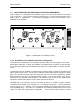
385700-4006-006 INTRODUCTION Transfer Relay Radiax RF Lightning Protection RF Lightning Protection Radiax Direction Control Direction Status +12 VDC Radiax Alarm Detector PA Alarm Detector PA Diplexer +12 VDC LNA Alarm Detector LNA -10 dBm Alarm & Control Interface Board Diplexer Pilot Tone Generator 24V Lightning Protectors Alarm & Control Connections +12 VDC AC-DC Power Supply AC Lightning Protection 87-265 VAC USER Control Equipment Figure 1-2 DLA Block Diagram Document use is rest
385700-4006-006 INTRODUCTION 1.4.2 Distribution Line Amplifier Major Components Refer to Figure 1-3 DLA Internal View for locations of major DLA components. The test point locations, Pilot Tone Output J3 on the Pilot Tone Board and Alarm and Control Interface Board Test Points J4, shown in Figure 1-3 are used for initial DLA adjustments and referenced later in this manual in section 2.5. J2 J1 J3 J6 J9 J4 J8 J7 J2 J5 J1 Lightning Protection Module Figure 1-3 DLA Internal View Refer to section 2.
385700-4006-006 1.5 INTRODUCTION EQUIPMENT CHARACTERISTICS Refer to Table 1-2 Distribution Line Amplifier Specifications. The table contains the specifications for the DLA. The table includes characteristics and specifications in three categories: technical, environmental, and physical. 1.5.1 Power and Utility Requirements The DLA operates across an AC input range of 87 to 265 VAC. required. No user adjustment is 1.5.
385700-4006-006 INTRODUCTION Electrical Specifications Channels 2 Channel 1, MHz 2416.64 ± 13.5 MHz Channel 2, MHz 2467.86 ± 13.
385700-4006-006 INSTALLATION CHAPTER 2 INSTALLATION 2.1 INSTALLING THE DISTRIBUTION LINE AMPLIFIER EQUIPMENT This chapter provides information to install the Distribution Line Amplifier (DLA) and to prepare the equipment for use. 2.1.1 Unpacking and Inspection Unpacking the Distribution Line Amplifier does not require special procedures. Use normal shop procedures to unpack the equipment. Carefully inspect the shipping containers and equipment.
385700-4006-006 INSTALLATION In normal usage, the RF connections to the Distribution Line Amplifier are made with non® radiating coaxial cable that is attached to the main radiating coaxial cable RADIAX . The non® radiating RF cable is type HELIAX LDF4-50A (or equivalent) with N male type connectors.
385700-4006-006 INSTALLATION FORWARD CONFIGURATION : DIRECTION CONTROL = NORMAL USER Control Equipment ® ALARM/CONTROL J2 HELIAX BDR 1 ® RADIAX ® ® RADIAX DLA NORM PA OUT2 J5 NORM PA OUT1 LNA IN J3 NORM PA IN LNA OUT J4 POWER IN J1 RADIAX DLA ALARM/CONTROL J2 ® HELIAX ® RADIAX NORM DET IN J6 ® NORM PA IN LNA OUT J4 NORM PA OUT2 ® J5 HELIAX NORM PA OUT1 LNA IN J3 POWER IN J1 NORM DET IN J6 RADIAX VAC Power BDR 2 ® RADIAX BDR 1 ZONE BDR 2 ZONE Figure 2-1 DLA Forward Direction
385700-4006-006 INSTALLATION USER Control Equipment ® ALARM/CONTROL J2 HELIAX BDR 1 ® RADIAX ® ® RADIAX DLA NORM PA OUT2 J5 NORM PA OUT1 LNA IN J3 NORM PA IN LNA OUT J4 POWER IN J1 RADIAX DLA ALARM/CONTROL J2 ® HELIAX ® RADIAX NORM DET IN J6 NORM PA IN LNA OUT J4 POWER IN J1 ® NORM PA OUT2 ® J5 HELIAX NORM PA OUT1 LNA IN J3 NORM DET IN J6 ® RADIAX RADIAX VAC Power BDR 2 ZONE BDR 1 ZONE Figure 2-2 DLA Forward Direction Interconnect Diagram RF Port J3 – LNA In J3 – Norm PA Out
385700-4006-006 INSTALLATION 2.3.1 Connector Pin-outs Refer to Figures Figure 2-3 and Figure 2-4 for the connector pin-out information for the Distribution Line Amplifier ports. Figure 2-3 DLA Input VAC Pin-outs shows the pin assignments for the Distribution Line Amplifier POWER IN connector. The DLA Power Connector is a MIL-C-26482, Series 2 connector. The connector is MS3474W14-4P or equivalent. Mating connectors are MS3475W14-4S, PV75W14-4S, or equivalent.
385700-4006-006 INSTALLATION Figure 2-4 DLA ALARM/CONTROL Port Pin-outs, shows the pin assignments for the Distribution Line Amplifier ALARM/CONTROL connector. Figure 2-4 DLA ALARM/CONTROL Port Pin-outs The Alarm/Control connector is a MIL-C-26482, Series 1 connector. The part is MS3124E2016P, KPSE07E20-16P, or equivalent. The mating connectors are MS3126F20-16S, KPSE06F20-16S, or equivalent. These are crimp connectors with a grommet seal and strain relief.
385700-4006-006 2.4 INSTALLATION DISTRIBUTION LINE AMPLIFIER COMPONENT JACK LOCATIONS The following paragraphs describe the purpose and location of the jacks for the Distribution Line Amplifier. Refer to Figure 2-5 DLA Assembly Jack Locations. The amplifier connector panel contains one data jack, ALARM/CONTROL (J2). The DLA exchanges status and control signals with USER control equipment over ALARM/CONTROL (J2) port.
385700-4006-006 2.5 INSTALLATION PREPARATION FOR USE CAUTION Before applying power to the Distribution Line Amplifier, securely connect the RF ports to 50-ohm terminations. Failure to observe these cautions can damage the equipment. 2.5.1 Distribution Line Amplifier Setup A Distribution Line Amplifier is part of a wayside antenna system; a RADIAX based signal distribution system. The amplifier provides signal gain to offset the signal loss of the system.
385700-4006-006 INSTALLATION 2.5.2 Distribution Line Amplifier Initial Operational Adjustments 2.5.2.1 Input AC Power The Distribution Line Amplifier AC power supply automatically senses the input AC voltage. The DLA input voltage range is 87-265 VAC. Refer to Table 1-2 Distribution Line Amplifier Specifications. 2.5.2.2 Power Amplifier (PA) Channel (Channel 1) The nominal output level of the PA channel, as set at the time of manufacturing, is set to +27 dBm (4 port) or +30 dBm (2 port).
385700-4006-006 INSTALLATION The spectrum analyzer, if used, should be configured as follows: Center Frequency 2416.64 MHz Span 2 MHz RBW 30 KHz VBW 3 Hz Ref. Level as required Attach a ≥ 10 dB, 2 watt or greater, power attenuator to the spectrum analyzer RF input. The direction control signal characteristics required will depend on the interface option installed. The direction must be set to the NORMAL state.
385700-4006-006 INSTALLATION Attach a voltmeter to J4-3 on the Alarm I/O board. (PA input alarm test point). TP1 or TP2 can be used as the ground connection. Refer to Figure 1-3 DLA Internal View for the location of the Alarm and Control Interface Board test points. Standard 0.080 test probes should be used for test points. Adjust R1 (Input Alarm Set) on the PA module for TP3 to go to the high condition (≥ 3 VDC), low (≤1 VDC), and then high again.
385700-4006-006 2.5.2.3 INSTALLATION Low Noise Amplifier (LNA) Channel (Channel 2) The nominal gain of the LNA channel, as set at the time of manufacturing, is set to 30 dB. The output alarm level is set for a threshold nominally 10 dB below the expected output pilot level. The expected signal input range is -40 to -90 dBm. If other settings are desired, the customer should contact Andrew with additional information when ordering the equipment.
385700-4006-006 INSTALLATION Center Frequency Span RBW VBW Ref. Level 2467 MHz 2 MHz 30 KHz 3 Hz as required Attach a 10 dB, 2 watt or greater, power attenuator to the spectrum analyzer RF input. The direction control signal characteristics required will depend on the interface option installed. The direction must be set to the NORMAL state.
385700-4006-006 2.5.2.3.3 INSTALLATION LNA Output Alarm Adjustment NOTE The previous step must be completed before adjusting the output alarm. Attach a voltmeter to J4-2 (LNA output Alarm test point) on the Alarm I/O board. TP1 or TP2 can be used as the ground connection. Adjust R2 on the LNA until the voltage on J4-2 goes high (≥ 3 VDC), low (≤ 1.0 VDC), and then high again.
385700-4006-006 INSTALLATION external test measurement cable losses are accounted for, the amplifier should be replaced. Contact Andrew for additional information. 2.5.3.1.2 PA Input Signal Alarm Attach a voltmeter to J4-3 on the Alarm I/O relay board (PA output alarm test point). TP1 or TP2 can be used as the ground connection. After removing the signal from the J4 (FWD IN/RVS OUT) port of the Distribution Line Amplifier Assembly verify that J4-3 is < 0.7 VDC. If J4-3 is > 1.
385700-4006-006 2.5.3.2 INSTALLATION Forward LNA Channel Verification Set the DLA direction to the forward direction. 2.5.3.2.1 LNA Output Level Verification Attach either a signal generator (frequency = 2467 MHz) or a MDR to J3 (FWD OUT/RVS IN) port of the Distribution Line Amplifier Assembly. Adjust the signal generator or BDR signal level at J3 to -50 dBm ± 1 dB.
385700-4006-006 2.5.3.3.2 INSTALLATION PA Input Signal Alarm Attach a voltmeter to J4-3 on the Alarm I/O relay board (PA output alarm test point). TP1 or TP2 can be used as the ground connection. After removing the signal from the J3 (FWD OUT/RVS IN) port of the Distribution Line Amplifier Assembly verify that J4-3 is < 0.7 VDC. If J4-3 is > 0.7 VDC and the Distribution Line Amplifier has not been tested for the forward direction, perform the steps outlined in section 2.
385700-4006-006 OPERATIONS CHAPTER 3 OPERATIONS 3.1 WIRING PROTECTION AND GROUNDING The Distribution Line Amplifier does not have controls and indicators accessible from the outside of the unit. The DLA has two 10 Ampere fuses F1 and F2 for wiring protection on the connector panel. Refer to Figure 3-1 DLA Connector Panel Layout. There is a ground stud on the DLA connector panel for a ground wire connection. Refer to Figure 3-1 DLA Connector Panel Layout.
385700-4006-006 3.2 OPERATIONS STARTUP AND SHUTDOWN PRODECURES The following procedures ensure that installation does not damage the equipment. 3.2.1 DLA Startup Refer to section 4.2.1, for procedures to properly install the DLA. Mount the DLA in the equipment room or in the tunnel with no connections made. To start the DLA perform the following: 1. 2. 3. ® Securely connect HELIAX cables to DLA J3 and J4 ports. Connect the USER control equipment to the DLA connector panel J2 port.
385700-4006-006 MAINTENANCE AND TROUBLESHOOTING CHAPTER 4 MAINTENANCE AND TROUBLESHOOTING 4.1 TROUBLESHOOTING Before beginning any in-depth troubleshooting, ensure that power is available to the unit. Ensure that all cable connections are secure. Table 4-1 DLA Fault Isolation, describes the troubleshooting procedures for the DLA. Locate the unit’s symptom in the Fault Indication column. The Fault Description column lists components or functions that can cause faults.
385700-4006-006 4.2 MAINTENANCE AND TROUBLESHOOTING CORRECTIVE MAINTENANCE This section describes the removal and replacement of the DLA. See Table 4-1 DLA Fault Isolation, to determine when to remove and replace a line replaceable unit (LRU). 4.2.1 Remove and Replace DLA Referring to Figure 4-1 Remove and Replace DLA, perform the following actions to remove the DLA (shown as Item 2) 1. Disconnect VAC power cable from DLA (2) POWER IN (3) port. 2.
385700-4006-006 MAINTENANCE AND TROUBLESHOOTING 1 2 7 3 6 4 5 Figure 4-1 Remove and Replace DLA Document use is restricted to that described on cover 4-3
5700-4006-006 4.3 MAINTENANCE AND TROUBLESHOOTING TEST PROCEDURES Refer to Table 4-2 Test Equipment, for a list of test equipment to perform the following test procedures. If necessary, substitute an equivalent to the equipment listed. The following test procedures help the user verify that a DLA is faulty. Return faulty amplifiers to Andrew Corporation for maintenance and repair. Refer to paragraph 2.1.1 for equipment return information.
385700-4006-006 MAINTENANCE AND TROUBLESHOOTING Remove the fuses from the holder. Measure the resistance across the fuses. If the resistance is > 1.0 ohms, replace the fuse. Reinstall the fuses in the DLA. If the fuses are operational and the power supply remains off, replace the Distribution Line Amplifier. 4.3.1.2 RADIAX Alarm Asserted Assertion of the RADIAX input alarm indicates a loss of signal (Signal Center Frequency is 2416.
385700-4006-006 MAINTENANCE AND TROUBLESHOOTING configuration sheet, the PA module alarm may be indicating a faulty setting on the output level monitor. Refer to section 2.5.2.2.4 for details on setting the output alarm. If the output level monitor is correctly configured, the Distribution Line Amplifier should be returned to Andrew Corporation. 4.3.1.3.3 Loss of Pilot Tone Signal In a correctly configured DLA, the pilot tone is monitored by the LNA output detector circuit.
385700-4006-006 ORDERING INFORMATION CHAPTER 5 ORDERING INFORMATION 5.1 PARTS LIST This chapter provides a list of replacement parts and mating connectors for the Distribution Line Amplifier assembly. It also provides vendor names and addresses. Table 1-1 – DLA Part Numbers lists the various versions of the DLA and their respective part numbers. Figure 1-1 Distribution Line Amplifier (4 port) shows all of the items on the list.
385700-4006-006 ORDERING INFORMATION Table 5-2 provides a list of replaceable parts and mating connectors for the amplifier assemblies.
385700-4006-006 MECHANICAL INFORMATION CHAPTER 6 MECHANICAL INFORMATION Figure 6-1 DLA Mechanical Outline Document use is restricted to that described on cover 6-1
385700-4006-006 CIRCUIT ALARM/CONTROL TEST CHAPTER 7 ALARM/CONTROL TEST CIRCUIT The following schematic can be used to construct a test fixture to control the direction of the DLA and to monitor the status of the various Figure 7-1 Document use is restricted to that described on cover 7-1
385700-4006-006 CIRCUIT ALARM/CONTROL TEST Document use is restricted to that described on cover 7-2
385700-4006-006 CIRCUIT ALARM/CONTROL TEST Document use is restricted to that described on cover 7-3
385700-4006-006 CIRCUIT ALARM/CONTROL TEST Document use is restricted to that described on cover 7-4
385700-4006-006 CIRCUIT ALARM/CONTROL TEST alarms. The test fixture connects to J2 Alarm/Control of the DLA. This test fixture requires an external 24 VDC supply. The circuit should be mounted within a metal enclosure so that the required cable shielding integrity is maintained.