
Technical information


OM93_Rev H Page 29 of 28
APPENDIX A: Sector Change Process
The following is a general explanation of the actions necessary for changing the 9.3m Tripod Mount from an
existing Azimuth range (sector) to a new sector.
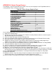
Table A.1: Sector Change Required Tools
Required Tool
Quantity
Spud Wrenches
2
1-7/16 Inch Open End Wrenches
2
1-5/8 Inch Open End Wrenches
2
1-5/8 Inch Socket for ¾” Drive
1
1-7/16 Inch Socket for ¾” Drive
1
3/4 Inch Drive Ratchet
1
9/16 Inch Wrenches
2
Come-along
2
Tag Lines
2
Experienced Riggers
2
Extension Ladder (Man lift recommended)
1
9/64 Inch Allen Wrenches
1 Set
1/2 Inch Wrenches
2
9/16 Inch Socket & Ratchet
1
Safety Harness
1 per installer
Hammer (Standard)
1
Replacement Hardware (A-325, etc.)
1 Set
Use the following procedure in order to perform a Sector Change:
1. Disable the Tracking System
2. Remove the vertical handrails for Maintenance Platform & Landing Platform (allows the antenna to go to a
high Elevation angle for less wind loads)
3. Loosen or remove the upper mechanical Elevation limit
4. Increase the Elevation angle to maximum, watching for interference near the Elevation Pivot Assembly
5. Retract the Azimuth Jackscrew within roughly 1 Foot of full retraction
6. Stabilize the reflector using the 2 come-alongs. Attach between the Panning Assembly Support Legs
(200107) & Rear Support Legs (200109). Repeat this step on the opposite side.
7. Loosen & remove the Jackscrew hardware between the Outrigger (200035) and Pivot Assembly (200022)
8. Using the Handwheel, adjust the Jackscrew to full retraction
9. Loosen & remove the Jackscrew Pivot Assembly hardware (except for the ½” x 2.25” Lg. Stud)
10. Remove any Maintenance Platform attachments, if present (for example, the ladder)
11. With rope, secure the Azimuth Jackscrew to the Landing Platform for safety
12. Slowly swivel the Jack & Azimuth Pivot Assembly (201021) toward opposite end of Panning Assembly until
the mount holes line up in Azimuth Pivot Assembly. Use spud wrench to assist further alignment as needed
13. Insert new/replacement A-325 Hardware, securing the Azimuth Pivot Assembly in its new position
14. Extend the Jackscrew
15. Swing the antenna, using come-alongs or tag lines to align the Jackscrew pivot connection with the
Panning Frame holes. Use spud wrench to assist further alignment as needed
16. Connect using the new/replacement hardware using the proper tensioning procedures