
Technical information


OM93_Rev H Page 15 of 28
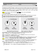
NOTE: it is more accurate and visually simple to minimize alternate set of transponder signals rather than maximizing the
transponder of interest.
Figure 3-4: Polarization at 45 Degrees from Optimum Setting
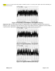
Step 9 of 9: With all 24 transponder signals of approximately equal amplitude appearing on the Spectrum
Analyzer screen, determine the specific antenna system and satellite parameters. Rotate the feed assembly as
required until the appropriate (odd or even) transponder signals have been maximized.
Figure 3-5: Maximizing Odd Transponders
Figure 3-6: Optimum Polarization Settings