9.3m Earth Station Antenna Assembly, Installation, Operations, & Maintenance Manual Document# OM93 – Revision H ASC Signal Corporation CANADA: 606 Beech Street Whitby, Ontario, Canada L1N 7T8 OM93_Rev H USA: 1120 Jupiter Rd. Ste.
OM93_Rev H Page 1 of 28
© 2010-11 ASC Signal Corporation All Rights Reserved. No part of this document may be photocopied, reproduced, stored in a retrieval system, or transmitted, in any form or by any means whether electronic, mechanical, or otherwise without the prior written permission of ASC Signal Corporation. ASC Signal Corporation reserves the right to change details in this publication without notice.
Table of Contents INTRODUCTION: How to Use This Manual 4 I.I Purpose & Overview 4 I.II Description I.III Miscellaneous Notices 5 I.IV Warning Symbols I.V Safety Terms Summary I.VI Summary of Safety Precautions I.VII Things to Never Do I.VIII Parts Verification 4 5 5 6 7 7 1.0 Recommended Tools & Foundation Preparation 8 1.1 Recommended Tools 1.2 A-325 Tensioning Procedure 1.3 Foundation Preparation 1.4 9.3m Assembly & Installation Reference Drawings 8 9 10 10 2.
List of Figures Figure 1-1a: Bolts Shorter than 4 Diameters Figure 1-1b: Bolts Longer than 4 Diameters Figure 1-2: Scraping Foundation Pads 9 9 10 Figure 3-1: Pure Noise Signal on Spectrum Analyzer Figure 3-2: Minimum Transponder Signal on Spectrum Analyzer Figure 3-3: Antenna Radiation Pattern Topographical Diagram w/ Plan View Figure 3-4: Polarization at 45 Degrees from Optimum Setting Figure 3-5: Maximizing Odd Transponders Figure 3-6: Optimum Polarization Settings 12 12 13 14 14 14 Figure 4-1: High-
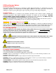
INTRODUCTION: How to Use This Manual I.I Purpose & Overview PURPOSE The scope of this manual is intended to provide station personnel with the base installation, operation, and maintenance requirements necessary for a 9.3-Meter C -Band Earth Station Antenna (9.3m ESA). This manual provides a convenient reference for authorized operator/service personnel requiring technical information on general system or specific subsystem equipment.
I.III Miscellaneous Notices Proprietary Information The technical data contained herein is proprietary to ASC Signal Corporation. It is intended for use in the installation, operation, and maintenance of ASC Signal equipment. This data shall not be disclosed or duplicated, in whole or in part, without the expressed written consent of ASC Signal Corporation.
The following safety symbols and terms may be used in this manual: Les symbols et les termes suivants de sûreté peuvant être employés en ce manuel: WARNING!/CAUTION! Statements identify conditions & practices that could result in injury or loss of life. AVERTISSEMENT! Les rapports d’avertissement identifient les conditions ou les pratiques qui pourraient avoir comme conséquence les dommages ou la perte de la vie. RISK OF ELECTRIC SHOCK! RISQUE DE DÉCHARGE ÉLECTRIQUE! I.
I.VII Things to Never Do NEVER touch circuits or reach into an enclosure until the disconnection of power and absence of charge has been confirmed NEVER service or adjust equipment alone. Electric shock can lead to cardiac arrest. Presence of immediate aid gives you a 90% chance of survival, but this drops by 10% with every passing minute. After 5 minutes resuscitation without permanent heart and/or brain damage is nearly impossible.
1.0 Recommended Tools & Foundation Preparation The following sections offer information related to preparing to assemble/install the 9.3m ESA, such as recommended tools, foundation preparation, & the details of the A-325 tensioning procedure required for the tightening of all A-325 hardware. 1.1 Recommended Tools ASC Signal supplies all appropriate hardware/parts required for installation of the 9.3m ESA. All tools needed for the installation process, however, should be provided by the installation crew.
Tin Snips Safety Gloves (per installer) Wax Stick Standard Standard Standard 1 1 1 (supplied) 1.2 A-325 Tensioning Procedure Throughout the installation instructions set forth in this manual, there will be references to the A-325 hardware tensioning procedure. A-325 hardware must be properly tensioned to avoid slippage between bolted surfaces under high loads. Slippage can cause the corresponding assembly to move or slip, resulting in antenna misalignment.
1.3 Foundation Preparation Before beginning the installation process on the ground mount assembly, ensure that the foundation has been prepared. Foundation specifications are provided by ASC Signal and may be used as a reference by civil engineering personnel when preparing the foundation for local soil conditions. These specifications are available before the shipment arrives by contacting the Customer Service Center or your Account Manager.
2.0 Mount & Antenna Assembly Procedures These sections provide the basic sequence and tips for the assembly of various elements of the 9.3m ESA. Appropriate drawings and schematics references for assembly of the antenna are also provided, when applicable. Refer to the drawings, instructions, and schematics for the specific system being installed, per the information provided in Table 1.2. 2.
3.0 Operation After completing the assembly of the antenna, the 9.3m ESA is ready to become operational. To operate the 9.3m ESA, it is necessary to direct it to the desired satellite and adjust both Elevation and Azimuth angles appropriately. These procedures provide details on how to correctly position the antenna on a desired satellite.
Step 2 of 9: With the antenna positioned in Azimuth, with the transponder signal maximized, follow the same procedure as in Step 1, only this time using the Elevation direction (scanning up-and-down). Once again, do this until the transponder signal has been maximized. Step 3 of 9: Repeat this procedure, alternating between the Azimuth and Elevation excursions of the antenna, until you have peaked the antenna transponder amplitude.
NOTE: it is more accurate and visually simple to minimize alternate set of transponder signals rather than maximizing the transponder of interest. Figure 3-4: Polarization at 45 Degrees from Optimum Setting Step 9 of 9: With all 24 transponder signals of approximately equal amplitude appearing on the Spectrum Analyzer screen, determine the specific antenna system and satellite parameters. Rotate the feed assembly as required until the appropriate (odd or even) transponder signals have been maximized.
3.2 Subreflector Adjustment After the satellite has been acquired and testing has taken place with the Spectrum Analyzer, the subreflector may need to be adjusted to maximize optimum performance of your antenna. The following procedures should be followed if a subreflector adjustment is required to maximize optimum performance. NOTE: All INTELSAT Type Approved antennas do not require subreflector adjustment.
4.0 Preventive Maintenance These sections contain periodic preventative maintenance instructions for the 9.3m Earth Station Antenna. Included are instructions for performing inspections, preventative maintenance procedures, and cleaning. NOTE: Refer to applicable vendor manuals for any repair procedures that are not included in this manual. These sections describe cleaning, inspections, and preventative maintenance procedures.
In the absence of any special inspection requirements, operational tests are the most effective means in isolating parts and assemblies requiring further inspection. During inspection, any noted damage and/or problematic condition which could preclude the continuation of proper operation (prior to the next scheduled inspection) should be recorded.
IF APPLICABLE, check that drain holes in bottom of the enclosure and pedestal are not obstructed, and there is no evidence of water accumulation. Check enclosure doors for proper closure. Verify door seals are intact and free of tears, abrasions, and/or other damage.
corrosion, imbedded dirt, grease, and oil deposits or the paint will not adhere to the surface. Lacquer thinner will dissolve paint if applied heavily and rubbed vigorously. Do not use bleach, soap solutions, or kerosene as it is difficult to remove the residue. Allow the clean surface to dry thoroughly before painting. Paint the cleaned surface with a zinc-rich paint. The paint can be applied with a brush, roller, or pressurized spray.
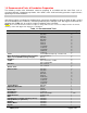
4.3.3 Lubrication For long life and trouble-free operation be certain not to extend the lubrication schedule beyond the frequency recommended in the Lubrication Chart. The frequency should be shortened if the antenna is subjected to an adverse environment (e.g., high temperature, extended periods of rainfall, high humidity, dust storms, etc).
Table 4.1: Lubrication Chart Lube Pt. # Components to be Lubricated 1 2 [1.] 3 [2.] 4 5 6 7 [1.] 8 [2.
Figure 4-1: High-Speed Antenna Lubrication Points OM93_Rev H Page 23 of 28
Figure 4-2: Medium-Speed Antenna Lubrication Points OM93_Rev H Page 24 of 28
4.4 Site Acceptance Test Procedure Once the installation procedure has been completed, and prior to turning over the system to the station facility, some form of Site Acceptance Test procedure will need to be performed, checked off, and signed by the responsible personnel and/or representative.
5.0 Corrective Maintenance & Troubleshooting The following sections will offer information, instructions, and guidelines regarding issues of corrective maintenance such as painting, backlash adjustment, and maintenance kits. 5.1 Top 5 ESA Maintenance & Troubleshooting FAQ 1. What should be done about chips, cracks, scratches, etc.
5.2.4 Prepping & Painting Galvanized Surfaces Remove all loose paint or rust using a scraper, wire brush, or sanding. Wipe clean the surface to be painted with a soft cloth rag and lacquer thinner. Allow the lacquer thinner to dry thoroughly before applying the finish coat of primer. Apply a zinc-rich paint as the final finish, thoroughly covering any previously primed surfaces. - - - - - - - - - - - - - - 5.2.
Figure 5-1: Jac/Jack Anti-Backlash Procedure 5.4 Maintenance Kits The below table provides descriptions of and ASC Signal part numbers for commonly used maintenance kits: Table 5.2: Maintenance Kits Part # 202436 239306 OM93_Rev H Description C-Band Feed Window Kit Lubrication Kit (5.6m – 9.
APPENDIX A: Sector Change Process The following is a general explanation of the actions necessary for changing the 9.3m Tripod Mount from an existing Azimuth range (sector) to a new sector. Table A.
APPENDIX B: Equipment Issues & Technical Support REPORTING EQUIPMENT LOSS OR DAMAGE If you find equipment was damaged during the shipping process, file a claim with the carrier. Follow the “Reporting Visible Loss or Damage” or “Reporting Concealed Damage” procedures to file a claim with a carrier. REPORTING VISIBLE LOSS OR DAMAGE Make a note of any loss or evidence of external damage on the freight bill or receipt, and have it signed by the carrier’s agent.