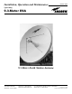
Installation, Operation and Maintenance Bulletin OM93 Revision D Type ES93( ) 9.3-Meter ESA 9.3-Meter Earth Station Antenna Andrew Corporation 10500 West 153rd Street Orland Park, IL U.S.A. 60462 Telephone: 708-349-3300 FAX (U.S.A.): 1-800-349-5444 Internet: http://www.andrew.com Customer Service, 24 hours: U.S.A. • Canada • Mexico: 1-800-255-1479 U.K.: 0800 250055 • Republic of Ireland: 1 800 535358 Printed in U.S.A.
Table of Contents Introduction How to Use This Manual Getting Started Installation Procedures Operation Preventive Maintenance Introduction. . . . . . . . . . . . . . . . . . . . . . . . . . . . . . . . . . . . . . . . . . . . . . . . . . . . . . . . . . . . . . . . . . . . . . . . 3 Proprietary Data . . . . . . . . . . . . . . . . . . . . . . . . . . . . . . . . . . . . . . . . . . . . . . . . . . . . . . . . . . . . . . . . 4 Information and Assistance. . . . . . . . . . . . . . . . . . . . . . . . .
9.3-Meter Earth Station Antenna Introduction Like all Andrew earth station antennas, the 9.3-Meter Earth Station Antenna provides high gain and exceptional pattern characteristics. The electrical performance and exceptional versatility provides the ability to configure the antenna with your choice of linearlyor circularly-polarized 2-port or 4-port combining network. That versatility is provided at the time of initial purchase, as well as in the future, as your satellite communication requirements evolve.
Proprietary Data The technical data contained herein is proprietary to Andrew Corporation. It is intended for use in operation and maintenance of Andrew supplied equipment. This data shall not be disclosed or duplicated in whole or in part without express written consent of Andrew Corporation. Information and Assistance Andrew Corporation provides a world-wide technical support network. Refer to the technical assistance portion of this this manual for the contact numbers appropriate to your location.
How to Use This Manual Overview The scope of this manual is intended to provide station personnel with the base installation, operation, and maintenance requirements necessary for a 9.3-Meter C-Band Earth Station Antenna. This manual provides a convenient reference for authorized operator/service personnel requiring technical information on general system or specific subsystem equipment.
Getting Started Overview The installation, operation, and maintenance of the 9.3-Meter Earth Station Antenna requires qualified and experienced personnel. Andrew installation, operation, and maintenance instructions are illustrated for such personnel. Additionally, the antenna should be inspected by qualified personnel to verify proper installation, maintenance, and condition of equipment as described in Preventive Maintenance.
NOTE: Failure to follow an installation procedure could result in damage to equipment or personal injury. Additional warnings will be displayed throughout this manual for your awareness. These warnings can be identified in warning boxes as shown in the following sample. Andrew disclaims any liability or responsibility for the results of improper or unsafe installation, operation, or maintenance practices.
Parts Verification Reporting Equipment Loss or Damage Reporting Visible Loss or Damage Andrew Corporation thoroughly inspects and carefully packs all equipment before shipment. If you find that there are missing components, please refer to page 9 for step-bystep instructions on how to properly report the equipment loss. If you find that there was damage caused to the equipment during the shipping process, a claim should be filed with the carrier.
Returning Equipment Andrew Corporation tries to ensure that all items arrive safe and in working order. Occasionally, despite these efforts, equipment is received which is not in working condition.
Installation Procedures Overview This section provides installation procedures for the 9.3-Meter Andrew Earth Station Antenna. The installation procedures include instructions on the following antenna components: • Mount • Reflector-to-Mount Assembly • Reflector • Enclosure Foundation Preparation • Subreflector • Feed System (C-band) Before beginning the installation process on the ground mount assembly, ensure that the foundation has been prepared.
A-325 Tensioning During the installation process, there are several references to the A-325 hardware tensioning procedure. The A-325 hardware must be properly tensioned to avoid slippage between bolted surfaces under high loads. Slippage can cause the corresponding assembly to move, causing antenna misalignment. When designated, the A-325 hardware should be tightened according to the following tensioning procedure. NOTE: Tensioned bolts are for final connections only and should not be loosened for reuse.
Tripod Ground Mount Assembly Azimuth Beam Assembly The three-point mount is an elevation-over-azimuth mount optimized for geostationary satellite applications. The mount enables continuous elevation adjustment from 0 to 90°. Azimuth adjustment is ±90° and divided into three 120° ranges with 30° overlap. Follow the subsequent procedures for proper installation of tripod ground mount assembly. Step 1 All ground mount hardware is type A-325. Lubricate all A325 bolt threads with supplied stick wax.
Step 4 Raise 201112 azimuth beam assembly and attach to front foundation pad as shown in Figure 5. • Use 1 in.
Support Legs Assembly Step 1 Attach 200068 joint assembly to 200114A beam assembly as shown in Figure 6. Attach 200083 angles to 200114A beam assembly as shown in Figure 6. • Use 7/8 x 2-1/4 in (57 mm) bolts and nuts for each connection Figure 6 Step 2 Attach 200088 joint assembly to 200114A beam assembly as shown in Figure 7.
Step 3 Raise 200114A beam assembly to upright position and attach 200109 supports to 200068 joint assembly as shown in Figure 8. • Use 7/8 x 2-1/4 in (57 mm) bolts and nuts • Insert bolts from 200068 joint assembly to supports • Supports should be installed back-to-back with the flat of angle facing upwards • Tighten supports until assembly can support itself Figure 8 Step 4 Attach 200063/200064 rear pad assemblies to 200109 supports as shown in Figure 9.
Step 5 Attach 200108 supports to 200063/200064 rear pad assemblies and 200088 joint assembly as shown in Figure 10. • Use 7/8 x 2-1/4 in (57 mm) bolts and nuts • Insert bolt from inside of joint assembly to outside of support • Supports should be installed back-to-back with the edges forward and the flats of angles facing rear Figure 10 Step 6 Attach 200873 supports between angle pairs as shown in Figure 11.
Step 7 Refer to Figure 12. Raise and attach assembled beam/support assembly to 200112 beam assembly using 7/8 by 2-1/4 in (57 mm) hardware and corresponding rear foundation pads as shown using 1 in flat washers and hex nuts. Ensure all A-325 mounting hardware is in place. Begin A-325 tensioning procedure at pads, and work upward. Note: Do not tighten 201022 pivot assembly hardware at this time.
Panning Frame Assembly Step 1 Refer to Figures 13A and 13B. Determine azimuth range requirements from APPENDIX ‘A’ (page 65) and loosely attach 200035 outrigger assembly (if required) to appropriate side of 200031A panning assembly. • Use 7/8 x 2-1/4 in (57 mm) hardware and apply supplied RTV to flange surfaces as indicated. Figure 13A Step 2 Step 3 Figure 13B Apply supplied RTV to flange surfaces and loosely attach 200022 pivot assembly to outrigge as shown.
Step 4 Refer to Figure 14. Apply supplied RTV to flange surfaces and loosely attach 200699/200021 elevation pivot assemblies to rear of enclosure drum assembly • Use 3/4 by 3.0 inch (75 mm) hardware 3/4 x 3” LG. (75 mm) 200031A Figure 14 Step 5 Slightly raising assembly and loosely attach 200016/200015 joint assemblies to bottom portions of panning assembly.
Step 6 Refer to Figure 15. Raise assembled panning/pivot assembly and loosely attach 301786 azimuth pivot assembly to upper portion of 200068 joint assembly as shown. • Use 7/8 by 2-1/2 inch (64 mm) hardware Note: Position mounting hardware as shown to ensure proper panning frame clearance. Install 7/8 inch flatwashers between 301786 pivot assembly and 200068 joint assembly.
Step 7 Refer to Figure 16. Attach 200107 support pairs back-to-back with 45967 spacer at midpoint. Loosely attach support pairs to corresponding tabs on 200015/200016 joint assemblies and 201022 pivot assembly as shown. • Use 7/8 by 2-1/4 in (57 mm) hardware Note: Angles are attached edge out with flat of angle facing inward. 301786 Step 8 Figure 16 Align panning frame/azimuth pivot assembly by swinging panning frame through its entire arc.
Azimuth Jack Screw Assembly Step 1 Refer to Figure 17. Apply RTV to flange surface and attach 200013-4/301841 azimuth jackscrew to 201021 azimuth pivot assembly as shown. • Use 1-1/4 by 3-1/2 in (89 mm) bolts, lock washers and nuts Note: Mounting hardware is included with corresponding jack assembly hardware kit. Figure 17 Step 2 Attach 200131 azimuth jack extension to 200013-4 azimuth jack screw (manual, low- and medium-speed applications only) as shown.
Step 3 Refer to Figure 18. Raise the azimuth pivot/jack screw assembly, and attach to 200088A joint assembly. • Use 1 by 2-1/2 inch (63 mm) hardware. Note: Mounting position of azimuth/pivot jack screw assembly is dependent upon azimuth range requirements and corresponds with mounting position of 200035 outrigger assembly (if utilized). Figure 18 Step 4 Refer to Figures 19A and 19B.
Figure 19A Figure 19B Step 6 Replace previously removed jack screw band clamp assembly. Note: Attach .jack extension to pivot assembly using 7/8 by 2-3/4 in (70 mm) bolts and nuts (P/O jack assembly hardware kit), for 200013-4 azimuth jack applications. For motorized mounts only, remove oil plug on motor assembly gearbox and replace with supplied vent plug packaged with the motor assembly. Note: Ensure hole in vent plug is positioned downward.
Elevation Jackscrew Assembly Step 1 Refer to Figure 20. Apply supplied RTV to indicated flange surfaces and attach 2000133/200048 elevation jack screw to 200128 elevation extension assembly as shown. • Use 1-1/4 by 3-1/2 in (89 mm) bolts, washers and nuts Note: Mounting hardware is included with corresponding jack assembly hardware kit. APPLY RTV APPLY RTV 3/4 x 3” LG.
Step 3 Refer to Figure 21. Apply supplied RTV to flange surface and attach remaining end of 200128 elevation extension assembly to corresponding 201022 pivot assembly as shown. • Use 7/8 by 2-1/4 in (57 mm) hardware. For motorized mounts only, remove oil plug on motor assembly gearbox and replace with supplied vent plug packaged with the motor assembly only after elevation jack is in final operating position. Note: Ensure hole in vent plug is positioned downward.
Grounding Cable Attachment Note: Thoroughly clean exposed portions of grounding cables, unplated portion of universal terminals and corresponding mounting surfaces using a wire brush. Liberally apply supplied 203233-2 conductive grease to all connection surfaces prior to and after installation. Thoroughly remove conductive grease from hands and tools using soap and water. Step 1 Refer to Figure 22.
Step 2 Refer to Figure 23. Remove existing 7/8 by 2-1/4 in (57 mm) hardware from both elevation pivot/joint assemblies at indicated positions and install grounding cables as shown. • Use supplied 7/8 by 2-3/4 in (70 mm) bolts and nuts Note: Supplied 3/4 in hardware is installed after reflector to ground mount installation. Figure 23 Step 3 Securely tighten all remaining ground mount/jack assembly hardware per hardware tensioning procedure.
Reflector/ Backstructure Assembly Feed Rotating Tube Assembly Step 1 Type A-325 hardware is utilized during the reflector attachment to the ground mount. Use of A-325 hardware eliminates slippage between mating surfaces under high loading conditions as well as the need for future retightening. Refer to the A-325 tensioning procedure in preceding installation text. CAUTION: Adhere to any special instructions stenciled on crate relative to crate opening, contents removal and/or personnel safety.
Step 2 Refer to Figure 25. Align tabs on feed rotating tube assembly 77639 or non-rotating tube 78334 with corresponding angle brackets on drum assembly. Apply supplied RTV as shown and attach rotating tube to center of drum assembly. • Use 3/8 x 1-1/2 in (38 mm) bolts, lock washers and nuts If 78334 non-rotating tube is used unbolt flange assembly, apply RTV to both flange faces and assemble to drum.
Jack Tripod Assembly Step 1 Refer to Figure 26. Assemble jack tripod by connecting tripod braces to tripod leg. • Use 3/4 x 5-1/2 in (140 mm) bolts, lock washers and nuts Step 2 Attach jack tripod assembly braces to corresponding drum pivot/mount assemblies as shown. • Use 3/4 x 2 in (51 mm) bolts, lock washers and nuts Figure 26 Step 3 Attach side plates to jack tripod assembly leg. • Use 1 x 2-1/2 in (64 mm) bolt, lock washer and nut Step 4 Attach side plates to drum tab.
Reflector Assembly Step 1 Refer to Figure 27. Assemble 20 right- and left-hand back-to-back strut assembly pairs Type 78082 and 78083 as shown. • Use 1/2 x 1-1/2 in (38 mm) bolts, spacers, lock washers and nuts. Tighten strut spacer bolt. Figure 27 Step 2 Refer to Figure 28. From inside of drum assembly, attach end of back-to-back strut assembly (slanted angles) to lower ring on drum assembly. • Use 1/2 x 4-1/2 in (114 mm) bolts, special washers, lock washers and nuts. Tighten until snug.
Step 3 Refer to Figure 29. Carefully remove reflector panel segments from packing crates. Begin with center flash panel (if applicable) and attach to corresponding angle tab on upper drum ring as shown. • Using 5/8 x 1-3/4 in (44 mm) bolt, spacer, lock washer and nut. Tighten the panel to drum angle hardware until lock washer is compressed, then back off one half turn. Do not over-torque. Note: Use 10 ft temporary support to raise outer portion of reflector segment.
Step 4 Refer to Figure 30. Install reflector segment formed tee section between corresponding back strut members and attach. • Use 1/2 x 1-7/16 in (37 mm) eccentric bolt, lock washer and nut Note: Ensure eccentric bolt is fully seated and bolt head marking is positioned at right angle to panel segment. It is recommended stick wax be applied to the shaft of the eccentric bolt to facilitate its insertion and later adjustment. All 20 eccentric bolt head markings must be at right angles to panel.
Step 6 Refer to Figure 32. Loosely attach 300177 Subreflector Strut Supports to reflector as shown ensuring brackets are installed on seam hole positions 15 and 16. Position brackets clockwise as shown using brackets and hardware supplied as part of 300175 Subreflector Strut Kit. Subreflector Assembly Step 1 Figure 32 Refer to Figure 33. Carefully remove subreflector subassembly and attached floating ring from wooden crate.
Step 2 Refer to Figure 34. Attach 300178 Subreflector Strut Brackets to 300174 Strut Assemblies. • Use 1/2 x 2-1/2 in (64 mm) galvanized bolts, 300022 backup plates, lock washers and nuts. Note: All strut brackets should face counterclockwise as shown. Figure 34 Step 3 Assemble 300174 strut assemblies as shown. • Use 300176 angles and 1/2 x 2 in (51 mm) galvanized bolts, lock washers and nuts. Step 4 Attach floating ring to corresponding strut brackets.
Step 7 Refer to Figure 35. Raise preassembled subreflector subassembly and strut assembly and attach to subreflector supports as shown. • Use 1/2 x 2-1/2 in (64 mm) galvanized bolts, flat washers, lock washers and nuts. Step 8 Securely tighten mounting hardware. Mount tabs on strut assemblies to right side of subreflector brackets to keep struts aligned with corresponding reflector segment sections.
Theodolite Assembly Refer to Figure 36. The Andrew Theodolite Kit (223711) contains 1 theodolite mounting assembly and 1 alignment stick assembly. A Wild T2 or Topcon DT-05A theodolite is used but not included as part of the Andrew Theodolite Kit. Note: The theodolite mounting assembly comes preassembled. The theodolite mounting assembly includes the lift/adapter flange mount assembly, X/Y translation stage and tribrach. Refer to the theodolite operation manual for theodolite operation instructions.
Step 2 Refer to Figure 37. Install theodolite support assembly to feed support tube. Secure theodolite support assembly by attaching lower flange adapter to feed support tube.
Theodolite Leveling Step 1 Refer to Figure 38. Assemble 3 brass rod holders as shown. The brass rod holders used for calibration of the theodolite to the reflector and subsequent alignment of the reflector, must be installed in the third seam holes at the panel seams shown. Step 2 Before taking any readings, allow the theodolite to become acclimated to ambient conditions for at least 15 to 20 minutes prior to operation.
Step 4 Refer to Figures 38 and 39. With the height of the theodolite and its support kit set as indicated in Figure 24, the theodolite should sight near the scribe line of the alignment stick when theodolite elevation is set to 90° 00’ 00”. If not, set the theodolite elevation angle to 90° and move the theodolite up or down until it sights on the scribe line using the rotary precision lift. Be careful not to turn entire torque tube while turning precision lift.
Theodolite Centering Step 1 Refer to Figures 38 and 39. Centering of the theodolite is performed using the X-Y translation stage. This device has 2 sets of micrometer adjustments and 2 sets of long locking adjustment screws which are opposed at 90°. Step 2 During initial adjustment, ensure that the long screws are unscrewed counterclockwise to provide free movement. Note: The screws will be utilized later to lock the device in place after the centering procedure is complete. Step 3 Refer to Figure 38.
Reflector Panel Adjustment Step 1 Refer to Figure 40. Each panel segment has a scribe line, which defines the circumference of all corresponding screw locations at the number 17 position. Step 2 Adjust panel segment using cambolts on back struts to move the panel to the highest possible position. Using the theodolite, target the surface of each panel segment at scribe line 17. Record these measurements for each cam bolt (Refer to Table 3). Average these values.
Table 3 44 Installation Procedures
Subreflector Adjustment Step 1 Refer to Figure 42. Use tape measure to set rim of subreflector to required distance of 119.110 in (302.6 cm) measured from the top of first seam hardware to the aperture plane of the subreflector using three subreflector adjustment studs. Step 2 Attach right angle viewing piece to theodolite. Move subreflector laterally to align the subreflector so it is centered with the theodolite while set at vertical (0° 00’ 00”).
Subreflector Offset Tilt Adjustment Step 1 Refer to Table 4 and Figure 43. Adjust top subreflector jam nuts (two) the distance indicated according to the offset pointing angle in Table 4. Make the desired adjustment using the floating ring and subreflector jam nuts. Note: Before making any adjustment, mark the starting position of the jam nuts in relation to the floating ring with a pencil, then mark the floating ring to indicate the proper distance of the turn.
Reflector/Backstructure to Ground Mount Assembly Installation Step 1 Refer to Figure 45. Attach 5/8 in (16 mm) shackles with corresponding 20 ft (6 m) chokers to four drum assembly angle brackets as shown. Attach 15 ft (4.5 m) tag line to forward left of jack tripod assembly. Note: Two front chokers should be approximately 4 in (102 mm) longer than rear chokers. Step 2 Extend azimuth jack until panning assembly is facing forward position (AZ = 0°).
Step 3 Refer to Figure 46. Extend elevation jack extension assembly to 7 ft (2 m) dimension as shown. Raise assembly and secure to forward ground mount beam assembly, using 6 ft (2 m) choker and winch assembly. Warning: Do not attempt to raise reflector/backstructure if winds exceed 25 mph. Raise reflector/backstructure assembly and align with corresponding elevation jack/panning frame assemblies using tag lines for guidance. Note: A minimum of three tag lines should be used during high wind conditions.
Operation Overview After you have completed the assembly of your antenna, you are now ready to become operational. In order to operate the earth station antenna, you will need to direct it to the desired satellite adjusting both the elevation and azimuth angles appropriately. The following procedures provide details on how to correctly position your antenna on the desired satellite. Acquiring A Satellite There are several procedures that may be used to properly acquire the satellite.
The following steps provide the procedure for acquiring a satellite. Step 1 Begin by obtaining the correct Az/El pointing data for the satellite of interest. Step 2 Using an inclinometer, position the antenna to the specified elevation angle. Step 3 Manually move the antenna in the azimuth (scanning back-and-forth around the direction of the specified azimuth angle) to achieve the maximum (greatest amplitude) transponder signals.
Step 7 Move the antenna in azimuth to obtain a null, then move ± in elevation to obtain a large peak signal. If not, move the antenna in the opposite azimuth direction through the peak and again move ± in elevation to obtain a large peak signal. If a larger peak is not found, you were on the main lobe.
Step 10 With all 24 transponder signals of approximately equal amplitude appearing on the spectrum analyzer screen determine the specific antenna system and satellite parameters. Rotate the feed assembly as required until the appropriate (odd or even) transponder signals are maximized.
Subreflector Adjustment After the satellite has been acquired and testing has taken place with the spectrum analyzer, the subreflector may need to be adjusted to maximize optimum performance of your antenna. The following procedures should be followed if a subreflector adjustment is required to maximize optimum performance. NOTE: All INTELSAT Type Approved antennas do not require subreflector adjustment.
Preventive Maintenance Overview This section contains periodic preventive maintenance instructions for the 9.3-Meter Earth Station Antenna. Included in this section are inspection and preventive maintenance procedures including cleaning and lubrication, painting, and an operational voltage/current checkout procedure deemed within the capabilities of the average station technician.
Mechanical Parts Clean mechanical parts by first removing dust, dirt, and other loose contaminants with a scraper, stiff brush (bristle or wire in the case of rust or other corrosion), or cloth or compressed air at 25 to 40 psi. Any accumulated imbedded dirt, corrosion, grease, or oil deposits that require further cleaning may be removed with a bristle or wire brush and a cleaning solvent such as trichlorethylene or equal.
• Check transformer for an excessive wax deposit on the surface, discoloration, or a pungent odor indicative of burning vanish denoting overheating or a total breakdown. • Check all terminal boards for broken or missing terminals and stripped threads. Check tightness of lead attaching hardware. • Check each starter for a make-after-break provision through the release of one pushbutton as the alternate pushbutton is pressed.
• Operate the azimuth and elevation drives as well as the feed rotation in both the plus and minus direction from the local control/motor drive controller at least once every three months during antenna down time. Check the mechanical limit switches provided at the end points stop the antenna and feed movement, and limit travel to prevent structural interference and damage.
• Check security of antenna mounting and interconnecting assembly hardware. Be certain all electrical grounding connections (including cross-axis grounding straps) are intact and secure, not corroded or broken. Thoroughly clean any noticeable corroded portions of grounding cables, unplated portion of universal terminals and corresponding mounting surfaces using a wire brush. Replace rather than tighten any loose A-325 structural hardware.
Step 4 Repeat preceding step (3) with the FEED CCW/OFF/CW switch in the alternate operating position. Step 5 Turn the AZIMUTH EAST/WEST switch to either position and while the antenna is rotating, carefully use a clamp on ammeter in accordance with the ammeter manufacturer’s instructions to take current readings off each of the three conductors (phases) connected to the load side of the azimuth drive motor circuit breaker.
Preservation of Component Parts Aluminum Parts When preserving the component parts, refer to the following paragraphs in this section. Remove all loose paint and corrosion by scraping, wire brushing, or using steel wool. If using steel wool near the feed window, make sure that none remains on the feed horn window. Edges of existing paint can be blended with the metal surface by using a fine grit sandpaper.
and remove any old lubricant to prevent an excessive build-up. Remove indicated access plugs from square tube weldment and apply lubricant to panning frame tube assembly and corresponding thrust pads. Securely replace access plugs in square tube weldment. Be certain to remove any protective caps and clean off each lubrication fitting prior to injecting fresh grease.
Lubrication Chart Lube Components Point to be No. Lubricated 1 Frequency (Months) 3 6 12 Type of Service Type of Lube No. of Lube Points or Quantity Pressure Fitting SHC32 1 1. Elevation Jackscrew Housing X 2.1 Elevation Jackscrew Gear Housing Fill and Drain I* C** Pipe Plugs SHC624 10 Oz 3.2 Elevation Drive Intermediate Gearbox Fill and Drain I* C** Pipe Plugs SHC624 34 Oz. 4. Elevation Jackscrew Pivot Pin, upper X Pressure Fitting SHC32 1 5.
Pressure Fitting 5 9 10 Pressure Fitting Worm Gear Polarization Pillow Drive Gear Blocks (2) Gearbox Fill Pressure Fitting 4 Gearbox Fill Gearbox Fill Heater Control Gearbox Level 1 2 3 Pressure Fitting Gearbox Drain Gearbox Level 6 7 8 Gearbox Fill Local Motor Control Note Medium-speed motors shown for illustrative purposes only.
Pressure Fitting 5 9 10 Pressure Fitting Worm Gear Polarization Pillow Drive Gear Blocks (2) Pressure Fitting 4 Heater Control Gearbox Drain 1 2 3 Pressure Fitting Gearbox Drain 6 7 8 Gearbox Level Local Motor Control Gearbox Level Medium-Speed Antenna Lubrication Points 64 Preventive Maintenance
APPENDIX ‘A’ dAZ = relative angle between true azimuth angle looking at satellite and mount pointing direction in degrees. This section contains the formulas for determining the pointing capabilities of the modular mount earth station antenna.
APPENDIX ‘B’ Sector Change Process The following is a generalized procedure of the actions required to change the 9.3M tripod mount from an existing azimuth range (sector) to a new one. (For example: from Azimuth range -60/+60 to -90/+30. Refer to APPENDIX ‘A’.) A. Tools Required: a. (2) Spud Wrenches b. (2) 1 7/16" open end wrenches c. (2) 1 5/8" open end wrenches d. 1 5/8" Socket for ¾" drive e. 1 7/16 Socket for ¾" drive f. ¾" Drive ratchet g. (2) 9/16" wrenches h. (2) come-alongs i. (2) Tag lines j.