
User's Manual


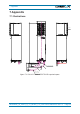


Table Of Contents
- 1. General
- 2. Introduction
- 3. Functional Description
- 4. Commissioning
- 4.1. General
- 4.2. High Power RU Mechanical Installation
- 4.3. Electrical Installation
- 4.3.1. Health and Safety for electrical installation
- 4.3.2. Property Damage Warnings for electrical installation
- 4.3.3. Connections
- 4.3.4. Grounding (Earthing)
- 4.3.5. Connection of the antenna cable
- 4.3.6. Mains power connection
- 4.3.7. Extension Unit port connection
- 4.3.8. External alarm In / Out port
- 4.3.9. RS 485 /+28 V port
- 4.3.10. Local interface port
- 4.3.11. Coupling Probe
- 4.3.12. Optical-fiber cable connection
- 4.3.13. Assembly instructions for optical LC patch cables
- 4.3.14. Optional equipment for optical fiber connection
- 4.4. Commissioning Flow-Chart
- 5. Alarms
- 6. Maintenance
- 7. Appendix
- 8. Index

7. Appendix
Page 54 M0200A8C_uc_ION-U_H_7P_80-85P_17P_19P User’s Manual for ION
®
-U
7.2. Specifications
This manual is valid for the following Remote Units:
ID No
Denomination
7698400-xxxx*
ION-U H 7P/80-85P/17P/19P
* The xxxx suffix is the identifier for the specific configuration of the Remote Unit.
Please refer to the ION-U H 7P/80-85P/17P/19P data sheet for the ION-U HP RU
specifications.
7.3. Spare Parts
Maintenance of the RU should be performed on an FRU (Field Replaceable Unit)
basis only. If any FRU not contained in the following list needs to be replaced, please
contact customer service for additional instructions.
Designation: ID No
Fan Unit M2-Cabinet
7661556-xx
Optical pigtail, 5 m
7704220
Optical pigtail kit, 5 m
7704209-xx
The manufacturer reserves the right to replace the spare parts listed above by
equivalent substitutes.
F Note: Only the spare part listed above is a FRU and can be replaced by the
user. For replacement of any other parts, please send the entire
Remote Unit back to the manufacturer.
7.4. List of Changes
Version
Changes
Release Date
M0200A8B
30-June-2015
M0200A8C
- chapter 1.4 adjusted
08-July-2015