
User's Manual


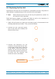


Table Of Contents
- 1. General
- 2. Introduction
- 3. Functional Description
- 4. Commissioning
- 4.1. General
- 4.2. High Power RU Mechanical Installation
- 4.3. Electrical Installation
- 4.3.1. Health and Safety for electrical installation
- 4.3.2. Property Damage Warnings for electrical installation
- 4.3.3. Connections
- 4.3.4. Grounding (Earthing)
- 4.3.5. Connection of the antenna cable
- 4.3.6. Mains power connection
- 4.3.7. Extension Unit port connection
- 4.3.8. External alarm In / Out port
- 4.3.9. RS 485 /+28 V port
- 4.3.10. Local interface port
- 4.3.11. Coupling Probe
- 4.3.12. Optical-fiber cable connection
- 4.3.13. Assembly instructions for optical LC patch cables
- 4.3.14. Optional equipment for optical fiber connection
- 4.4. Commissioning Flow-Chart
- 5. Alarms
- 6. Maintenance
- 7. Appendix
- 8. Index

6. Maintenance
M0200A8C_uc_ION-U_H_7P_80-85P_17P_19P User’s Manual for ION
®
-U Page 51
6.2. Replacing the Fan Unit
Replacement of the fan unit is not required as a preventative measure. Only when an
alarm indicates a malfunctioning of a fan, must the unit be exchanged.
F Note: Please observe that the fan unit can only be replaced as a whole. Do
not remove the fans separately.
Read and observe chapter 1.2 Health and Safety as well as the instructions in
chapter 6.1 General before starting with the replacement.
1. Switch off the Remote Unit. Make sure that mains power is disconnected for the
following replacement procedure. Then, proceed as follows:
2. Unscrew the four Pan-head screws
(
two at each side of the cabinet) and
remove the fan cover.
3. Unscrew and disconnect the fan
connector and unscrew the four Pan-
head screws the fan plate is fastened
to the cabinet. Take out the
fan unit,
replace it by the new one, fasten the
four Pan-
head screws for the fan unit,
re-
connect the fan connector and
mount the cover to the cabinet.
Fan connector