
User's Manual


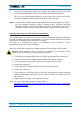
Table Of Contents
- 1. General
- 2. Introduction
- 3. Functional Description
- 4. Commissioning
- 4.1. General
- 4.2. High Power RU Mechanical Installation
- 4.3. Electrical Installation
- 4.3.1. Health and Safety for electrical installation
- 4.3.2. Property Damage Warnings for electrical installation
- 4.3.3. Connections
- 4.3.4. Grounding (Earthing)
- 4.3.5. Connection of the antenna cable
- 4.3.6. Mains power connection
- 4.3.7. Extension Unit port connection
- 4.3.8. External alarm In / Out port
- 4.3.9. RS 485 /+28 V port
- 4.3.10. Local interface port
- 4.3.11. Coupling Probe
- 4.3.12. Optical-fiber cable connection
- 4.3.13. Assembly instructions for optical LC patch cables
- 4.3.14. Optional equipment for optical fiber connection
- 4.4. Commissioning Flow-Chart
- 5. Alarms
- 6. Maintenance
- 7. Appendix
- 8. Index

4. Commissioning
Page 38 M0200A8C_uc_ION-U_H_7P_80-85P_17P_19P User’s Manual for ION
®
-U
4.3.10. Local interface port
The Local Interface port is a RJ45 network port, which can be used for a local
connection to a laptop PC. This interface is used by factory for the initial setup of the
RU.
Front View
RJ45
Pin
Assignment
1
TXD+
2
TXD-
3
RXD+
4
5
6
RXD-
7
8
figure 4-20 Local interface connector
table 4-6 Local interface
connector pinning
4.3.11. Coupling Probe
The coupling probe is a QMA measurement probe that allows the measurement of
the antenna output without disconnecting the antenna. The coupling is as follows:
Port
Coupling dB typ.
700 MHz
57
800/850 MHz
56
1900 MHz
50
1700 MHz
48