
User's Manual


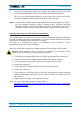
Table Of Contents
- 1. General
- 2. Introduction
- 3. Functional Description
- 4. Commissioning
- 4.1. General
- 4.2. High Power RU Mechanical Installation
- 4.3. Electrical Installation
- 4.3.1. Health and Safety for electrical installation
- 4.3.2. Property Damage Warnings for electrical installation
- 4.3.3. Connections
- 4.3.4. Grounding (Earthing)
- 4.3.5. Connection of the antenna cable
- 4.3.6. Mains power connection
- 4.3.7. Extension Unit port connection
- 4.3.8. External alarm In / Out port
- 4.3.9. RS 485 /+28 V port
- 4.3.10. Local interface port
- 4.3.11. Coupling Probe
- 4.3.12. Optical-fiber cable connection
- 4.3.13. Assembly instructions for optical LC patch cables
- 4.3.14. Optional equipment for optical fiber connection
- 4.4. Commissioning Flow-Chart
- 5. Alarms
- 6. Maintenance
- 7. Appendix
- 8. Index

4. Commissioning
M0200A8C_uc_ION-U_H_7P_80-85P_17P_19P User’s Manual for ION
®
-U Page 37
4.3.8. External alarm In / Out port
The Alarm port provides external alarm contacts (two inputs and two outputs) that are
used to monitor and report alarms generated by other equipment or to provide
contact closures for RU alarms. The connector is an 8-pin Binder 712 series
connector.
Front View
8-Pin Binder 712 Series
Pin
Assignment
1
EXT_IN_1
2
GND_Isolated
3
EXT_IN_2
4
EXT_Out_1_normally
closed
5
EXT_Out_1_common
6
EXT_Out_2_normally
open
7
EXT_Out_2_common
8
EXT_Out_2_normally
closed
figure 4-18 Alarm connector
table 4-4 Alarm connector
pinning
4.3.9. RS 485 /+28 V port
This 5 pin connector provides RS 485 communications and +28 VDC power.
Front View
5-Pin Binder 712
Series
Pin
Assignment
1
+28V/500 mA
2
GND
3
RS485_RD-
4
RS485_RD+
5
GND
figure 4-19 RS485 /+28 VDC connector
table 4-5 RS485/+28V
pinning
5
4
3
2
1
B0405AFA
1
B0405AEA
2
3
4
5
6
7
8