
User's Manual


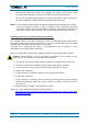
Table Of Contents
- 1. General
- 2. Introduction
- 3. Functional Description
- 4. Commissioning
- 4.1. General
- 4.2. High Power RU Mechanical Installation
- 4.3. Electrical Installation
- 4.3.1. Health and Safety for electrical installation
- 4.3.2. Property Damage Warnings for electrical installation
- 4.3.3. Connections
- 4.3.4. Grounding (Earthing)
- 4.3.5. Connection of the antenna cable
- 4.3.6. Mains power connection
- 4.3.7. Extension Unit port connection
- 4.3.8. External alarm In / Out port
- 4.3.9. RS 485 /+28 V port
- 4.3.10. Local interface port
- 4.3.11. Coupling Probe
- 4.3.12. Optical-fiber cable connection
- 4.3.13. Assembly instructions for optical LC patch cables
- 4.3.14. Optional equipment for optical fiber connection
- 4.4. Commissioning Flow-Chart
- 5. Alarms
- 6. Maintenance
- 7. Appendix
- 8. Index

4. Commissioning
Page 34 M0200A8C_uc_ION-U_H_7P_80-85P_17P_19P User’s Manual for ION
®
-U
4.3.6.2. Mains power connection DC
Caution: Danger of electrical hazard by high current. Disconnect mains
power before opening the DC connector housing.
Note: The Mains cable must be properly secured observing loc
al regulations and
electrical codes. Be sure to allow enough slack in the cable at the RU to
mount or
dismount the cable into the DC Mains connector of the RU.
Unscrew the two M3 x 12 captive screws
and take off the cover from the DC Mains
connector housing.
At the RU housing
the cover is inserted into a recess, so first
lift the cover at the front and carefully pull
it out from the recess.
Then remove the rubber plug.
Double lug DC cable connectors need to
be M6 with a stud hold spacing of 15.88
mm (5/8”).
Rubber
plug