
User's Manual

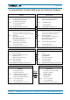


Table Of Contents
- 1. General
- 2. Introduction
- 3. Functional Description
- 4. Commissioning
- 4.1. General
- 4.2. High Power RU Mechanical Installation
- 4.3. Electrical Installation
- 4.3.1. Health and Safety for electrical installation
- 4.3.2. Property Damage Warnings for electrical installation
- 4.3.3. Connections
- 4.3.4. Grounding (Earthing)
- 4.3.5. Connection of the antenna cable
- 4.3.6. Mains power connection
- 4.3.7. Extension Unit port connection
- 4.3.8. External alarm In / Out port
- 4.3.9. RS 485 /+28 V port
- 4.3.10. Local interface port
- 4.3.11. Coupling Probe
- 4.3.12. Optical-fiber cable connection
- 4.3.13. Assembly instructions for optical LC patch cables
- 4.3.14. Optional equipment for optical fiber connection
- 4.4. Commissioning Flow-Chart
- 5. Alarms
- 6. Maintenance
- 7. Appendix
- 8. Index

4. Commissioning
Page 20 M0200A8C_uc_ION-U_H_7P_80-85P_17P_19P User’s Manual for ION
®
-U
3. Hang the Remote Unit into the upper bracket, insert it into the lower bracket, and
fasten it to the lower bracket with the M8x25 screws (C), split lock washers (D)
and washers (E), see chapter 4.2.3.
The maximum diameter of the pole or column must not exceed 120 mm (4.7 inch).
figure 4-5 Pole mounting – max. diameter
4.2.5. Pole mounting procedure with brackets
The pole-mounting kit with brackets includes
• two mounting brackets (A), two counter brackets (B), four threaded bolts (C),
flat (F) and split lock (G) washers, hexagon (E) and locking (D) nuts to mount
the brackets to the pole
• and two M8x25 screws (H), flat (F) and split lock (G) washers to attach the
Remote Unit to the bracket.
figure 4-6 Pole mounting – with brackets
1
2
0
m
a
x
.