
User's Manual

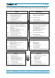


Table Of Contents
- 1. General
- 2. Introduction
- 3. Functional Description
- 4. Commissioning
- 4.1. General
- 4.2. High Power RU Mechanical Installation
- 4.3. Electrical Installation
- 4.3.1. Health and Safety for electrical installation
- 4.3.2. Property Damage Warnings for electrical installation
- 4.3.3. Connections
- 4.3.4. Grounding (Earthing)
- 4.3.5. Connection of the antenna cable
- 4.3.6. Mains power connection
- 4.3.7. Extension Unit port connection
- 4.3.8. External alarm In / Out port
- 4.3.9. RS 485 /+28 V port
- 4.3.10. Local interface port
- 4.3.11. Coupling Probe
- 4.3.12. Optical-fiber cable connection
- 4.3.13. Assembly instructions for optical LC patch cables
- 4.3.14. Optional equipment for optical fiber connection
- 4.4. Commissioning Flow-Chart
- 5. Alarms
- 6. Maintenance
- 7. Appendix
- 8. Index

3. Functional Description
M0200A8C_uc_ION-U_H_7P_80-85P_17P_19P User’s Manual for ION
®
-U Page 15
The unit utilizes a single fiber to support multiple bands in both the uplink and
downlink directions. WDM (Wave Division Multiplex) filters are integrated in the
optical modules. For the UL, a wavelength within 1546 nm – 1550 nm is used. For
the DL, a wavelength of 1310 ±10 nm is used. The maximum optical output power for
the UL and DL is 6.7 mW.
3. Functional Description
figure 3-1 ION-U High Power RU block diagram
In the Downlink (DL) path, the Remote Unit provides:
• Optical to RF conversion of the input optical signal
• Automatic Gain Control (AGC) of each converted signal to compensate for
optical losses
• RF amplification of the converted RF signal for transmission while maintaining
an excellent signal-to-noise ratio
• RF filtering to reject spurious emissions
In the Uplink (UL) path, the Remote Unit provides:
• RF amplification to boost the signals received by the antennas to maintain an
excellent signal-to-noise ratio
• RF filtering to reject spurious emissions
• Automatic Level Control (ALC) to adjust the RF signal level to meet blocking
requirements
• RF-to-optical conversion of the signal, which is conveyed to the optical port
The Remote Unit can be paired with further EUs (Extension Unit) to provide
additional bands.
o
e
o
e
WDM
DL
UL
UL/DL
700 MHz
800-850 MHz
1900 MHz
UL
Amp
From / To
Mobile Station
From / To
Master Unit
LC/APC 8°
Optical Transceiver
(OTRx)
Power Amplifier
Duplexer Unit
4.3-10 Connector
From / To
Extension Unit
2100 MHz
UL
Amp
Diplexer Unit