
Installation Instruction
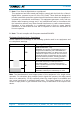
Table Of Contents
- 1. General
- 2. Introduction
- 3. Functional Description
- 4. Commissioning
- 4.1. General
- 4.2. High Power EU Mechanical Installation
- 4.3. Electrical Installation
- 4.4. Commissioning Flow-Chart
- 5. Alarms
- 6. Maintenance
- 7. Appendix
- 8. Index

Figures and Tables
M0200A9C_uc_ION-U_EU_H_7P_80-85P_17P_19P User’s Manual for ION
®
-U Page 5
FIGURES AND TABLES
figure 3-1 ION-U High Power EU block diagram ....................................................... 15
figure 4-1 Maximum distance between RU and EU .................................................. 18
figure 4-2 Wall mounting - pitches ............................................................................ 19
figure 4-3 Pole mounting - pitches ............................................................................ 20
figure 4-4 Pole mounting - screw bands ................................................................... 20
figure 4-5 Pole mounting - fasten EU ........................................................................ 20
figure 4-6 Pole mounting – max. diameter ................................................................ 21
figure 4-7 Pole mounting – with brackets .................................................................. 21
figure 4-8 Pole mounting - pitches ............................................................................ 22
figure 4-9 Pole mounting - brackets .......................................................................... 22
figure 4-10 Pole mounting - fasten EU ...................................................................... 22
figure 4-11 ION-U EU H 7P/80-85P/17P/19P AC version connector flange ............. 24
figure 4-12 ION-U EU H 7P/80-85P/17P/19P DC version connector flange ............. 26
figure 4-13 Grounding bolts ...................................................................................... 27
figure 4-14 Grounding bolt, schematic view .............................................................. 27
figure 4-15 Mains power connector .......................................................................... 34
figure 4-16 Mains power cable - AC ......................................................................... 34
figure 4-17 EU (Extension Unit) connector ............................................................... 37
figure 4-18 EU connector and cable bridge .............................................................. 37
figure 4-19 Mounting the EU cable bridge ................................................................ 38
figure 7-1 ION-U EU H 7P/80-85P/17P/19P required space..................................... 45
table 4-1 Specified torques ....................................................................................... 17
table 4-2 ION-U EU H connector flange ................................................................... 25
table 4-3 AC power cable pinning ............................................................................. 34
table 4-4 EU connector pinning ................................................................................ 37