
Installation Instruction
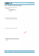
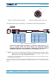
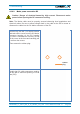
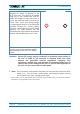
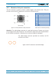
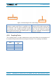
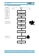
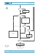
Table Of Contents
- 1. General
- 2. Introduction
- 3. Functional Description
- 4. Commissioning
- 4.1. General
- 4.2. High Power EU Mechanical Installation
- 4.3. Electrical Installation
- 4.4. Commissioning Flow-Chart
- 5. Alarms
- 6. Maintenance
- 7. Appendix
- 8. Index

4. Commissioning
Page 38 M0200A9C_uc_ION-U_EU_H_7P_80-85P_17P_19P User’s Manual for ION
®
-U
figure 4-19 Mounting the EU cable bridge
Take the cable bridge connector at the
connector coupler and insert it carefully to the
EU connector
. Use the green markings to align
the connector,
turn it without pressure until the
noses catch the notches and carefully push it at
right angle into the connector.
Then take the cable bridge
connector (Pin-
holder) and push it
into the EU connector until the lock
clicks.
The red ‘UNLOCK’ marking
must be completely covered by the
connector coupler.
4.3.8. Coupling Probe
The coupling probe is a QMA measurement probe that allows the measurement of
the antenna output without disconnecting the antenna. The coupling is as follows:
Port
Coupling dB
typ.
700 MHz
57
800/850 MHz
56
1900 MHz
50
1700 MHz
48
Connector coupler
Pin-holder