
Installation Instruction
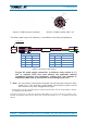
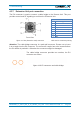
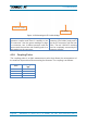
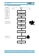
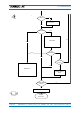
Table Of Contents
- 1. General
- 2. Introduction
- 3. Functional Description
- 4. Commissioning
- 4.1. General
- 4.2. High Power EU Mechanical Installation
- 4.3. Electrical Installation
- 4.4. Commissioning Flow-Chart
- 5. Alarms
- 6. Maintenance
- 7. Appendix
- 8. Index

4. Commissioning
M0200A9C_uc_ION-U_EU_H_7P_80-85P_17P_19P User’s Manual for ION
®
-U Page 37
4.3.7. Extension Unit port connection
The EU connector is used to connect a cable bridge to the Remote Unit. This port
provides control and RF signaling to and from the Extension Unit.
Front View
7-Pin
Pin
Assignment
1
RF
2
n.c.
3
System Bus
4
RF (if Pin installed)
5
System Bus
6
n.c.
7
RF
figure 4-17 EU (Extension Unit) connector table 4-4 EU connector pinning
Attention: The cable bridge connector is a push-pull connector. Ensure not to insert
it at an angle into the EU connector. The connector coupler has to be inserted before
the Pin-holder is pushed in. Otherwise the connectors might be damaged.
The cable bridge connector provides two notches, the EU
connector two noses.
figure 4-18 EU connector and cable bridge