
Installation Instruction
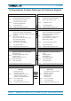
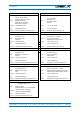
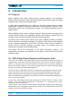
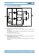
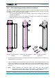
Table Of Contents
- 1. General
- 2. Introduction
- 3. Functional Description
- 4. Commissioning
- 4.1. General
- 4.2. High Power EU Mechanical Installation
- 4.3. Electrical Installation
- 4.4. Commissioning Flow-Chart
- 5. Alarms
- 6. Maintenance
- 7. Appendix
- 8. Index

3. Functional Description
M0200A9C_uc_ION-U_EU_H_7P_80-85P_17P_19P User’s Manual for ION
®
-U Page 15
3. Functional Description
figure 3-1 ION-U High Power EU block diagram
In the Downlink (DL) path, the Extension Unit provides:
• Automatic Gain Control (AGC) of each converted signal to compensate for
optical losses
• RF amplification of the converted RF signal for transmission while maintaining
an excellent signal-to-noise ratio
• RF filtering to reject spurious emissions
In the Uplink (UL) path, the Extension Unit provides:
• RF amplification to boost the signals received by the antennas to maintain an
excellent signal-to-noise ratio
• RF filtering to reject spurious emissions
• Automatic Level Control (ALC) to adjust the RF signal level to meet blocking
requirements
700 MHz
800-850 MHz
1900 MHz
UL
Amp
From / To
Mobile Station
Power Amplifier
Duplexer Unit
4.3-10 Connector
From / To
Remote Unit
2100 MHz
UL
Amp
Diplexer Unit
Frequency
Conversion Unit
f
2
f
1
f
2
f
1
f
2
f
1
f
2
f
1