
User's Manual


4. Commissioning
MF0200A5C_ION-U_L_7_80-85_17EP_19P.docx Manual for ION
®
-U Page 39
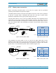
4. Wire the power cable to the junction box or receptacle. Refer to the color code
and pin numbers shown in figure 4-19 (AC cable), figure 4-20 (DC cable), or
figure 4-21 (Vdc/100 cable) depending on the type of power supply used by
the unit.
5. With the cable’s Mains plug disconnected from the RU, turn the circuit breaker
on, unscrew the plug’s protective cover, and carefully test the plug with a
voltmeter to ensure that the voltage and polarity are correct.
6. Once the testing has been completed, turn off the circuit breaker.
7. Unscrew the protective cover from the Mains connector of the unit.
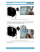
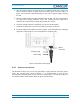
8. Insert the plug into the Mains connector (figure 4-22) and tighten the clamping
ring until it is hand tight. Do not over-tighten the clamping ring.
figure 4-22 Connect mains plug
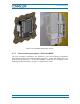
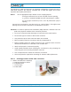
4.2.6. Antenna connection
The Remote Unit has one 4.3-10 (1-st generation: N-type) antenna connector (figure
4-23). For mounting the cable connector, it is recommended to refer to the
corresponding documentation of the connector manufacturer. The bending radius of
the antenna cables must remain within the given specifications.
Clamping ring
Mains plug
Mains
connecto
r