
User's Manual


4. Commissioning
MF0200A5C_ION-U_L_7_80-85_17EP_19P.docx Manual for ION
®
-U Page 37
4.2.5. Mains power connection
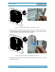
Before connecting electrical power to the units, the system must be grounded
(earthed) as described in the previous chapter.
The Mains power must be connected to the Mains connector of the unit for operation
of the RU. A power cable is delivered with each RU. The type of power cable
delivered is dependent on the type of power supply in the unit.
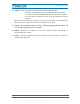
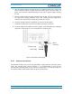
The AC power cable is a 3.2 m (10.5 ft) 16 AWG cable with a 4-pin Amphenol C016
series plug on one end to connect to the RU Mains connector. The other end of the
cable is un-terminated with 3 end splices to connect to the AC power source. A 10 m
(33.7 ft) AC power cable is also available as an option. The AC power cable is shown
in figure 4-19.
4-Pin Amphenol C016
Series
Pin Name Color
1 Phase Black
2 Neutral White
3 n.c. n.c
4 Ground Green
figure 4-19 AC power cable table 4-3
AC power cable
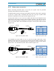
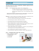
The standard DC power cable is a 3.2 m (10.5 ft) 13 AWG cable with a 4-pin
Amphenol C016 series plug on one end to connect to the RU Mains connector. The
other end of the cable is un-terminated with 2 end splices to connect to the -48 Vdc
power source. The standard DC power cable is shown in figure 4-20.
4-Pin Amphenol C016
Series
Pin Name Color
1 n.c n.c
2 –48V Black
3 0V Red
4 n.c. n.c
figure 4-20 DC power cable table 4-4
DC power cable
black
A
m
phenol 4-Pin
female connector
Protective Cap
3x end splice
white
green
B0400A4
A
RU Mains
Connector
4
3
2
1
black
Amphenol 4-Pin
female connector
Protective Cap
2x end splice
red
B0400A5A
RU Mains
Connector
4
3
2
1