
User's Manual


3. Functional Description
Page 20 MF0200A5C_ION-U_L_7_80-85_17EP_19P.docx Manual for ION
®
-U
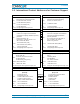
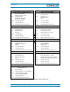
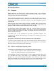
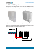
Mains Connector
The RU receives its power through the Mains connector . The type of connector is
dependent on the RU model. A 4-pin Amphenol connector is used for AC models and
standard DC models. A 7-pin Amphenol connector is used for DC models powered
by a dual cable supply.
Antenna Port
The RU has one duplex 4.3-10 (1-st generation RUs: N-female) antenna port for
transmitting and receiving signals to and from distributed antennas. This RF port can
be connected directly to an antenna (i.e. using RF jumper cables) or through splitters,
allowing additional antennas to be fed by the RU.
Probe
This port is used as measurement probe to antenna port.
Local Port RS-232
The RS-232 port is standard DB-9 female connector used for external modem
communication with an optional Extension Unit.
Status LED
The status LED provides a visual warning of an alarm condition. The color of the
LED indicates the severity of the alarm.
Pwr/Ctrl Connector
The Pwr/Ctrl connector supports an optional fan unit. The RU provides power and
fan speed control to the fan unit and receives alarms from it through this 7-pin Binder
connector.
Alarm Connector
The RU has two alarm relay inputs that can be used to monitor and report alarms
from external devices. The alarm connector is a 5-pin Binder connector.
Expansion Ports
The Expansion UL and Expansion DL ports are QMA female connectors that
are used to connect to a CommScope EU to provide additional bands.
Optical Ports
The LC-APC optical connectors are used to send and receive the signals between
the RU and the Master Unit’s OTRx modules.
The DL optical port receives downlink signals from the MU OTRx.
The UL optical port transmits uplink signals to the MU OTRx.
A
C
D
E
F
G
H
I
J
K