Optical Remote Unit ION™-M7P/85P/17P/19P (ML-Cabinet) User's Manual MF0143AUA
User’s Manual for ION™-M7P/85P/17P/19P (ML-cab) © Copyright 2011 CommScope, Inc. All rights reserved. Andrew Solutions is a trademark of CommScope, Inc. All information contained in this manual has been revised thoroughly. Yet Andrew Solutions accepts no liability for any omissions or faults. Andrew Solutions reserves the right to change all hard- and software characteristics without notice.
TABLE OF CONTENTS 1. GENERAL 7 1.1. USED ABBREVIATIONS 7 1.2. HEALTH AND SAFETY WARNINGS 8 1.3. ABOUT ANDREW SOLUTIONS 10 1.4. INTERNATIONAL CONTACT ADDRESSES FOR CUSTOMER SUPPORT 12 2. INTRODUCTION 15 2.1. PURPOSE 15 2.2. THE ION™-M7P/85P/17P/19P (INTELLIGENT OPTICAL NETWORK; MMR) 15 3. COMMISSIONING 17 3.1. 3.1.1. 3.1.2. 3.1.3. MECHANICAL INSTALLATION General Wall-Mounting Procedure Pole-Mounting Procedure 17 17 19 20 3.2. 3.2.1. 3.2.2. 3.2.3.
User’s Manual for ION™-M7P/85P/17P/19P (ML-cab) 4.6. TROUBLESHOOTING 40 5. MAINTENANCE 41 5.1. GENERAL 41 5.2. REPLACING THE FAN UNIT 42 5.3. CLEANING THE HEAT SINK 43 6. APPENDIX 45 6.1. ILLUSTRATIONS 45 6.2. 6.2.1. 6.2.2. 6.2.3. SPECIFICATIONS Electrical Specifications Mechanical Specifications Environmental and Safety Specifications 46 46 46 46 6.3. SPARE PARTS 47 7. INDEX Page 4 49 MF0143AUA.
FIGURES AND TABLES figure 3-1 Mounting bracket installation .................................................................... 19 figure 3-2 RU mounting ............................................................................................ 19 figure 3-3 Pole-mounting kit...................................................................................... 20 figure 3-4 Connector flange of ION-M7P/85P/17P/19P ............................................ 23 figure 3-5 RS485 connector..................
User’s Manual for ION™-M7P/85P/17P/19P (ML-cab) For your notes: Page 6 MF0143AUA.
1 General 1. GENERAL 1.1.
User’s Manual for ION™-M7P/85P/17P/19P (ML-Cab) 1.2. HEALTH AND SAFETY WARNINGS 1. Only suitably qualified personnel is allowed to work on this unit and only after becoming familiar with all safety notices, installation, operation and maintenance procedures contained in this manual. 2. Read and obey all the warning labels attached to the unit. Make sure that the warning labels are kept in a legible condition and replace any missing or damaged labels. 3.
1 General 11. Use this equipment only for the purpose specified by the manufacturer. Do not carry out any modifications or fit any spare parts which are not sold or recommended by the manufacturer. This could cause fires, electric shock or other injuries. 12. Due to power dissipation, the repeater may reach a very high temperature. Do not operate this equipment on or close to flammable materials. 13. Before opening the unit, disconnect power supply. 14.
User’s Manual for ION™-M7P/85P/17P/19P (ML-Cab) 1.3. ABOUT ANDREW SOLUTIONS Andrew Wireless Systems GmbH based in Buchdorf/ Germany, is a leading manufacturer of coverage equipment for mobile radio networks, specializing in high performance, RF and optical repeaters. Our optical distributed networks and RF repeater systems provide coverage for every application: outdoor use, indoor installations, tunnels, subways and many more.
1 General Page 11
User’s Manual for ION™-M7P/85P/17P/19P (ML-Cab) 1.4. INTERNATIONAL CONTACT ADDRESSES FOR CUSTOMER SUPPORT Americas: Canada United States Andrew Solutions Canada Andrew Solutions, Andrew LLC, A CommScope Company Mail 620 North Greenfield Parkway Garner, NC 27529 U.S.A. Mail 620 North Greenfield Parkway Garner, NC 27529 U.S.A. Phone +1-905-878-3457 (Office) +1-416-721-5058 (Mobile) Phone +1-888-297-6433 Fax +1-905-878-3297 Fax +1-919-329-8950 E-mail Peter.Masih@commscope.com, WIsupport.
1 General Europe: United Kingdom France Andrew Solutions UK Ltd CommScope France Mail Unit 15, Ilex Building Mulberry Business Park Fishponds Road Wokingham Berkshire RG41 2GY England Mail Immeuble Le Lavoisier 4, Place des Vosges 92052 Courbevoie France Phone +44-1189-366-792 Phone +33-1 82 97 04 00 Fax +44-1189-366-773 Fax +33-1 47 89 45 25 E-mail WIsupport.uk@commscope.com E-mail WIsupport@commscope.
User’s Manual for ION™-M7P/85P/17P/19P (ML-Cab) For your notes: Page 14 MF0143AUA.
2 Introduction 2. INTRODUCTION 2.1. PURPOSE Cellular telephone systems transmit signals in two directions between a base transceiver station (BTS) and mobile stations (MS) within the signal coverage area. If weak signal transmissions occur within the coverage area because of indoor applications, topological conditions or distance from the transmitter, extension of the transmission range can be achieved by means of an optical distribution system.
User’s Manual for ION™-M7P/85P/17P/19P (ML-Cab) The ION is easily set-up and supervised via a graphical user interface (GUI). Remote units can be commissioned through the use of built-in test equipment. An autoleveling function compensates for the optical link loss making installation easy and quick. The entire system may be monitored remotely via an Andrew OMC. This platform uses SNMP protocol and is compliant to X.733 standard.
3 Commissioning 3. COMMISSIONING 3.1. MECHANICAL INSTALLATION 3.1.1. General Read the health and safety warnings in chapter 1.2 Health and Safety Warnings. 1. Do not install the unit in a way or at a place where the specifications outlined in the Environmental and Safety Specifications leaflet of the supplier are not met. 2. It is recommended only to use the mounting hardware delivered by the supplier.
User’s Manual for ION™-M7P/85P/17P/19P (ML-Cab) A spacing of 40 mm (1.58 inch) around the unit is required. 7. To ensure sufficient airflow when mounting the unit in enclosed spaces, two lid openings (one for the air inlet and the other for the air outlet) have to be provided. Do not block these air inlets and outlets when mounting the Remote Unit. The size of each opening must equal at least 17 x 17 cm (290 cm2). Make sure, too, there is no thermal short circuit between the air inlet and air outlet.
3 Commissioning 3.1.2. Wall-Mounting Procedure Check the suitability of the wall-mounting kit and the wall. Mark the position of the drilling holes (for measurements and a more detailed description refer to the wall mounting plan that is part of the delivery). Drill four holes at the marked positions and insert dowels*. Screw the mounting brackets to the wall / dowels using the four dowel screws as illustrated in figure 3-1 Mounting bracket installation.
User’s Manual for ION™-M7P/85P/17P/19P (ML-Cab) 3.1.3. Pole-Mounting Procedure The standard mounting hardware also includes all parts required for pole mounting: figure 3-3 Pole-mounting kit Use the screw bands to fasten the two mounting brackets to the pole. ) Note: When fastening the mounting brackets make sure that they are installed congruently and not at an angle to each other. To determine the distance between the beams, refer to the wall mounting plan that is part of the delivery.
3 Commissioning 3.2. ELECTRICAL INSTALLATION 3.2.1. General Read the health and safety warnings in chapter 1.2 Health and Safety Warnings. 1. This unit contains dangerous voltages. Loss of life, severe personal injury or property damage can be the result if the instructions contained in this manual are not followed. 2. Ground the unit before connecting power supply. A grounding bolt is provided on the cabinet to connect the ground-bonding cable. 3.
User’s Manual for ION™-M7P/85P/17P/19P (ML-Cab) 13. Observe the labels on the front panels before connecting or disconnecting any cables. Page 22 MF0143AUA.
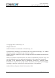
3 Commissioning 3.2.2. Connections Alarm output connector Status LED Optical-fiber connector Antenna connector Alarm input connector Power supply connector RS485 / 232 connector Grounding bolt figure 3-4 Connector flange of ION-M7P/85P/17P/19P Control Connector (RS485 / RS232) This 8-pin male connector (type: Binder Series 712) primarily supports control of the Extension Unit via RS485 bus.
User’s Manual for ION™-M7P/85P/17P/19P (ML-Cab) 3.2.3. Grounding Grounding must be carried out. Connect an earth-bonding cable to the grounding connection provided at the outside of the Remote Unit (see chapter 3.2.2 Connections). Do not use the grounding connection to connect external devices. figure 3-6 Grounding bolt figure 3-7 Grounding bolt, schematic view After loosening the hex nut, connect the earth-bonding cable between the two washers as illustrated in the figures above.
3 Commissioning To minimize passive inter-modulation (PIM) distortion, attention has to be paid to the physical condition of the connector junctions. Do not use connectors that show signs of corrosion on the metal surface. Prevent the ingress of water into the connector. Attach and torque the connectors properly. 3.4. POWER CONNECTION Before connecting electrical power to the units, the system must be grounded as described in the previous chapter.
User’s Manual for ION™-M7P/85P/17P/19P (ML-Cab) * Mains power must be interruptible with an external power supply breaker. For the power supply breaker, observe the following recommendation: 120 Volt / 20 Amp max. or 240 Volt / 16 Amp, single-phase, 50 / 60 Hz AC service is needed, i.e. the external AC breaker should be 20 Amps max. for 120-Volt service or 16 Amps for 240-Volt service. For the DC power supply, observe the local regulations of the DC service provider. 3.5.
3 Commissioning Before connecting the fiber cables, follow the procedure below to ensure optimized performance. It is important for these procedures to be carried out with care: ¾ Remove fiber-optic protective caps. ¾ Do not bend the fiber-optic cable in a tight radius (< 4 cm) as this may cause cable damage and interrupt transmission.
User’s Manual for ION™-M7P/85P/17P/19P (ML-Cab) 5. If the connector is still dirty, repeat the dry cleaning technique. 6. Inspect the connector. 7. If the connector is still dirty, clean it with 99% isopropyl alcohol (wet cleaning) followed immediately with a dry clean in order to ensure no residue is left on the endface. 8. Repeat steps 5 through 7 until endface is clean. Note: For a more detailed description please refer to: http://www.cisco.
3 Commissioning 3.5.1. Protective Plug Connection: A protective plug is provided for the connection of the fiber-optic cables. figure 3-9 Protective-plug assembly ) Note: Only high-quality connectors must be used for this type of plug. Qualified brands are Diamond or Huber & Suhner.
User’s Manual for ION™-M7P/85P/17P/19P (ML-Cab) For plug assembly, observe the following instruction: 1. Pass one or two contacts through the backshell and the clamp ring. 2. Place the contact(s) on the lower insulation body by pushing the groove of the contact into the cavity. If there is only one contact, cavity A must be used. * 3. Then, mount the upper insulation body on the lower insulation body. ** Upper insulation body Cavity B Cavity A 4. Bring the insulator into the plug.
3 Commissioning 7. Bring the plastic ring over the cable(s), push it into the backshell and compress the seals and plastic ring by screwing the clamp ring tight (no gap) using a spanner with opening 20. *** Screw tight until gap is closed 8. Connect the plug to the optical-fiber 9. To lock the connector, push the black connector of the Remote Unit, again locking ring forward.**** by fitting a stamp on the plug into the groove of the connector.
User’s Manual for ION™-M7P/85P/17P/19P (ML-Cab) Protective plug Fiber cable Ring 3/4 Reducer Screw the reducer to the protective plug backshell without any gap! Coupling Place the appropriate seal parts (with) one groove for one contact or two grooves for two contacts) over the cable(s) and push them into the backshell! Protective tube Push the fiber-optic cable carefully through the tube until it comes out at the other end. G1055M0 figure 3-10 Tube-kit installation Page 32 MF0143AUA.
3 Commissioning 3.6. COMMISSIONING Read the health and safety warnings in chapter 1.2 Health and Safety Warnings as well as the description carefully to avoid mistakes and proceed step by step as described! Do not operate the Remote Unit without terminating the antenna connectors. The antenna connectors may be terminated by connecting them to their respective antennas or to a dummy load.
User’s Manual for ION™-M7P/85P/17P/19P (ML-Cab) Commissioning an ION-M Remote Unit Manual for Remote Unit Philips screwdriver Mounting kit Spanner, size 13 mm Drilling machine Dowels Screw driver Screw driver Spanner, size 13 mm Start Preperation Unpack RU, RU accessories and mounting kit. Mechanical installation Fasten wall or pole mounting kit to wall or pole. Mechanical installation Mount RU to mounting kit, ensure suffient air flow and avoid thermal short circuits.
3 Commissioning LED on? No Check power switch inside RU (RUs with door). Check mains cabling. Check mains power. Yes LED status Red Internal Error Change power supply (RUs with a door). Reduce environmental temperature. Eliminate thermal short circuit. Disconnect and connect mains. Fans should run. If not, replace the fans at RU. MU: Change amplifier setting at MU controller Orange Yellow Yes LED status Red Green Spare RU available? External error Close the door (RUs with a door).
User’s Manual for ION™-M7P/85P/17P/19P (ML-Cab) For your notes: Page 36 MF0143AUA.
4 Alarms 4. ALARMS 4.1. BITE AND ALARMS The Built-In Test concept comprises the monitoring of the power supplies, the power amplifiers and the optical interface. All occurring alarms can be checked via software at the Master Unit. 4.2. HANDLING OF ALARMS As soon as the software acknowledges a valid alarm, a message is transmitted to the Master Unit. If the reason for the alarm has been cleared or if the alarm should continue, a new alarm message will not be repeated.
User’s Manual for ION™-M7P/85P/17P/19P (ML-Cab) Red Status LED off Alarms directly related to RU: Change power supply (RUs with door). Power 28 V Replace the affected Remote Unit. Reduce environmental temperature. Temperature Eliminate thermal short circuit. Disconnect and connect power supply. Fan Fans should run. If not, replace the fans at RU. I²C Disconnect and connect power supply. Optical alarm Tx Exchange RU. Amplifier “Power (MU: Change amplifier setting at MU Down” controller).
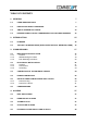
4 Alarms 4.5. EXTERNAL ALARM INPUTS AND OUTPUTS G1038Z0 figure 4-1 Flange connector, 5 poles G1038Z0 figure 4-2 Flange connector, 7 poles The alarm outputs (open collector output 5 V / 1 mA) are normally low. In case of an alarm they are high active (5 V). They can be used to monitor alarms with an external alarm indicator. The +28 V pin (for its location see figure 4-2 Flange connector, 7 poles) is protected by a 500 mA thermoswitch.
User’s Manual for ION™-M7P/85P/17P/19P (ML-Cab) With the external alarm inputs it is possible to monitor the status of connected devices, e.g. a UPS, via software. All alarm inputs are normally high (5 V) without connection. The polarity (high/ low) can be set via the software at the Master Unit (for details please see according software manual). The device to be monitored must be connected so that the alarm contacts will be closed in case of an alarm (I max = 8 mA).
5 Maintenance 5. MAINTENANCE 5.1. GENERAL Read the health and safety warnings in chapter 1.2 Health and Safety Warnings. ) Note: The Remote Unit does not require preventative maintenance measures. ) Note: To prevent malfunctions of the cooling system due to dirt or pollution, it is recommended to clean the heat sink at regular intervals. These cleaning intervals depend mainly on the location of the Remote Unit and the corresponding degree of pollution.
User’s Manual for ION™-M7P/85P/17P/19P (ML-Cab) 5.2. REPLACING THE FAN UNIT Replacement of the fan unit is not required as a preventative measure. Only if an alarm indicates a malfunctioning of a fan, must the unit be exchanged. ) Note: Please observe that the fan unit can only be replaced as a whole. Do NOT remove the fans separately! Read the health and safety warnings in chapter 1.2 as well as the instructions in chapter 5.1 General before starting with the replacement. 1.
5 Maintenance 5.3. CLEANING THE HEAT SINK To avoid a malfunctioning of the Remote Unit, the heat sink should be cleaned in case of pollution. In order to prevent any damage, proceed as explained in the following. ) Note: Read the health and safety warnings in chapter 1.2 Health and Safety Warnings as well as the instructions in chapter 5.1 General before starting with the replacement procedure. Then, proceed as follows: 1. Switch off the Remote Unit.
User’s Manual for ION™-M7P/85P/17P/19P (ML-Cab) For your notes: Page 44 MF0143AUA.
6 Appendix 6. APPENDIX 6.1.
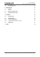
User’s Manual for ION™-M7P/85P/17P/19P (ML-Cab) 6.2. SPECIFICATIONS 6.2.1. Electrical Specifications ION-M7P/85P/17P/19P Electrical Mains power 115 Vac or 230 Vac Power supply Power consumption 1050 W Optical Connectors E2000/APC 8° Optical return loss 45 dB min. Fiber type Single mode E9/125 mm Optical link budget 0 dB to 10 dB All figures are typical values, unless otherwise stated All data is subject to change without notice. 6.2.2.
6 Appendix 6.3. SPARE PARTS The following lists contain all parts available for the Remote Unit. The configuration of the delivered unit meets the requirements of the customer and can differ depending on the state of the delivery. Maintenance of the ION-M7P/85P/17P/19P should be performed on an FRU (Field Replaceable Unit) basis only. Do not damage the warranty labels on the components, as this voids the warranty.
User’s Manual for ION™-M7P/85P/17P/19P (ML-Cab) For your notes: Page 48 MF0143AUA.
7 Index 7. INDEX A H Abbreviations Used ................................................ 7 Address of Andrew Wireless Systems GmbH....... 13 Alarms Alarm Status .................................................... 37 Bite and Alarms ............................................... 37 External Inputs........................................... 39, 40 Handling of Alarms .......................................... 37 List ................................................................... 40 Outputs ..........