
User's Manual

4. Alarms and Troubleshooting
Page 34 MF0145ASA.docx User’s Manual for ION
®
-M7HP/85HP EU
4. Alarms and Troubleshooting
All alarms occurring can be checked via software at the Master Unit to where a
message is transmitted when the software acknowledges a valid alarm.
A new alarm message will not be repeated if the reason for the alarm is cleared or if
the alarm continues.
A new alarm message will be generated if the alarm is interrupted for at least five
seconds after acknowledgement.
Refer to the corresponding software documentation of the Master Unit for details.
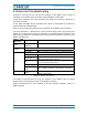
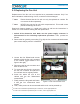
For local supervision, a status LED on the connector flange of the unit (position see
section 3.2.3 Connections) gives an indication of possible reasons for alarms. This
table shows possible on-site measures that could be checked before referring to the
Master Unit alarm list.
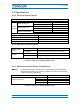
Status LED
Indication
Alarms Possible on-site measures
Green
No alarm
Status ok
Orange
Alarms not directly related to RU:
ALC alarm
(MU: Decrease DL input power of affected band).
Red
Alarms directly related to EU:
Power 28 V Replace the affected unit.
Temperature
Reduce environmental temperature.
Eliminate thermal short circuit.
Fan
Disconnect and connect mains. Fans should run.
If not, replace the fans at RU.
I²C Disconnect and connect mains.
Amplifier “Power
Down”
(MU: Change amplifier setting at MU controller).
Status LED
off
Mains
Check mains cabling.
Check mains power.
table 4-1 Status LED alarms
The status of the Extension Unit can be checked via the Master Unit (for details
please refer to the software manual of the Master Controller).
Explicit troubleshooting is also available in the MU software (software manual or
WEB Interface).