
User's Manual

3. Commissioning
MF0145ASA.docx User’s Manual for ION
®
-M7HP/85HP EU Page 31
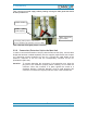
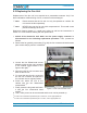
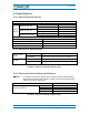
Then, connect your local supply cable by feeding it through a cable gland that should
at least provide IP55:
Then, close the cover again (torque: 1.45 N-m).
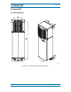
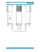
3.2.9. Connection Extension Unit to the Main Unit
In order to connect the Extension Unit (EU) with the Remote Unit (RU), use the cable
bridge that has been ordered separately from the supplier (requirements see chapter
3.1.3 Mounting Distance between RU and EU). Connect this cable bridge at the
extension connector of the RU with the corresponding connector at the EU
(illustrated in figure 3-9).
Attention: To prevent damaging the connectors of the extension port, align the
plug end of the connector properly before inserting. Do not twist the
connector. When the connector is in place, tighten the screws in a
clockwise direction. Particular attention must be paid plugging this
connector to maintain the ingress protection class of the Remote Unit.
Cable gland
(IP55 required)
Mains cable to RU
(pre-installed)
Local supply cable (minimum cross section:
6.6 mm² (
≥ AWG 9) per potential / 9 mm² for cable)
Torque: 6.5 N-m