
User's Manual

3. Commissioning
Page 18 MF0145ASA.docx User’s Manual for ION
®
-M7HP/85HP EU
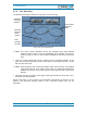
3.1.4. Wall-Mounting Procedure
Check the suitability of the wall-mounting kit and the wall.
Mark the position of the drilling holes (for measurements and a more detailed
description refer to the wall mounting plan that is part of the delivery).
Drill four holes at the marked positions and insert dowels*.
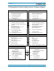
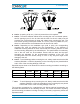
Screw the mounting brackets to the wall / dowels using the four dowel screws as
illustrated in figure 3-2 Mounting bracket installation.
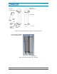
For each bracket, first screw in the 2 washers, then the 2 spring washers, then
the 2 M8x80 screws (see also figure 3-2 Mounting bracket installation).
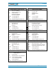
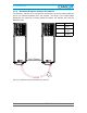
Hang the Remote Unit into the upper mounting bracket at a slight angle and let it
move smoothly towards the wall so that it engages firmly into the brackets (see
figure 3-3 RU wall mounting). Then, screw the unit to the lower mounting bracket
using 2 of the M8x25 screws that are part of the delivery (4 are provided).
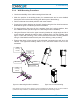
Ensure that there is free access to the electrical connections as well as to the
cabinet. The approved bending radius of the connected cables must not be
exceeded.
figure 3-2 Mounting bracket installation figure 3-3 RU wall mounting
* The dowels are not part of the delivery since the suitable type depends on the on-site conditions
(material of wall). Therefore, use dowels that are appropriate for the mounting surface.
M8 screws
S
p
rin
g
washer
Washer
Position of
dowels *
Upper
mounting
bracket
Lower
mounting
bracket