
User's Manual


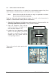
Table Of Contents

External-Alarm Inputs
with Optocouplers
Variant A)
External-Alarm Outputs with Optocouplers
Connector Pin Description Connector Pin Description
1 IN1_EXTERNAL 1 OUT1_EXTERNAL
2 IN2_EXTERNAL 2 OUT2_EXTERNAL
3 IN3_EXTERNAL
3 OUT3_EXTERNAL
4 IN4_EXTERNAL
4 OUT4_EXTERNAL
5
5
6 6
7
7
X13
1)
=
INPUTS
8
GND_ISOLATED
X19
2)
=
OUTPUTS
8
GND_ISOLATED
1)
Voltage: 0 - 5 V;
Current: max. 7 mA (on each input)
2)
Pull up tied to +5 V (on each output)
Voltage: 0 V or +5 V; I
sink max.
= 2 mA;
Alarm active high
Variant B:
External-Alarm Outputs with Relays
Connector Pin Description
1 OUT1_NC
2 OUT2_NC
3 OUT3_NC
4 OUT4_NC
5 OUT1_NO
6 OUT2_NO
7 OUT3_NO
8 OUT4_NO
9 OUT1_CO
10 OUT2_CO
11 OUT3_CO
X14
3)
=
OUTPUTS
12 OUT4_CO
3)
Voltage: +28 V, current: max. 0.4 A
table 5 3 External-alarm inputs and outputs, PIN assignment
Relay Contacts on the External-Alarm Output
Page 37 MF0145A8A_FCC modif.doc
figure 4-3 External-alarm outputs, relay contacts in alarm condition
1)
NC = abbrev. of "Normally Closed (contact)" (a.ka. break contact)
In non-energized position of the relay, this contact is closed and opens after coil energization
2)
NO = abbrev. of "Normally Open contact (a.k.a. make contact),
In non-energized position of the relay, this contact is open, and will be closed after coil energization.
3)
CO = abbrev. of "Change Over (contact (a.ka. double throw)
This contact is the common contact configuration comprising both NC and NO contacts electrically
connected. With switching, the CO contact changes between NC and NO.
External-Alarm Output
Output voltage: 28 Vdc
Output current: 0.5 A
NO = Normally Open
2
)
CO =
Change Over
3)
("common")
NC = Normally Closed
1
)
In non-energized position /
alarm condition