
User's Manual


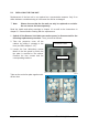
Table Of Contents

Page 36 MF0145A8A_FCC modif.doc
figure 4-1 External-alarm inputs and outputs, location
4.5.2. Layout and Connector Description
* in standard version X14 is not equipped
G3194X006
figure 4-2 Application board, connectors
Ext. alarm
inputs
X13
Application board
X19
Ext. alarm out
p
uts
X14
P3348B0
X13
I
2
C BBU
FAN
OTRx 2 OTRx 1
Ext.
Alarm
INPUT
Ext.
Alarm
OUT
X14 *
Core
module 1
Core
module 2
X19
LED DOOR only for maintenance
RS232
LOCAL 1
I
2
C external
not equipped
RS232
LOCAL 2