
User's Manual


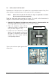
Table Of Contents

4.5. APPLICATION BOARD
4.5.1. External-Alarm Inputs and Outputs
There are four alarm inputs and four alarm outputs. The alarm outputs are potential-
free relay contacts. They can be used to monitor alarms with an external-alarm
indicator. Each alarm output can be set individually to any alarm at the Remote Unit.
For details please refer to the according chapter in the software manual of the master
unit.
Note: The manufacturer / supplier of this system accepts no liability for
damage caused by equipment connected to external outputs or by
effects from such equipment.
With the external-alarm inputs, it is possible to monitor the status of connected
devices, e.g. a UPS, via software. All alarm inputs are normally high (5 V) without
connection.
The device to be monitored must be connected so that the alarm contacts will be
closed in case of an alarm (0-5 V, max. 7 mA each input)
The location of the external-alarm inputs and outputs is illustrated in the following
chapter 4.5.2 Layout and Connector Description. Settings have to be done via the
ION-M Master Controller and are described in the according software documentation.
Please note that at the Remote Unit (RU), the external-alarm inputs (outputs-
optocoupler version) are optically decoupled.
Designation of External-Alarm Connectors for the ION-M7HP/7HP/85HP/19P (in
the W-cabinet):
X13 & X19 => alarm inputs and outputs with optocoupler
X13 & X14 => alarm inputs with optocoupler, alarm outputs with relays
Standard version: Optocoupler outputs => relays not equipped
Page 35 MF0145A8A_FCC modif.doc
The connecting clamps for the external alarm
inputs and alarm outputs are located at the
lower left-hand side (when standing in front of
the opened RU base) of the application board
For the layout of the application bard please
refer to the illustration in chapter 4.5.2 Layout
and Connector Description and/ or to that in
chapter 3.2.9 Connection of External-Alarms
Cable, bullet point 7) For the exact designation
of the connectors, please see pic
ture to the left-
hand side.
X13
Position
of
X14
X19