
Installation Instructions


6. Notice: If any different or additional mounting material is used, ensure that the mounting
remains as safe as the mounting designed by the manufacturer. The specifications for
stationary use of the Remote Unit must not be exceeded. Ensure that the static and
dynamic strengths are adequate for the environmental conditions of the site. The mounting
itself must not vibrate, swing or move in any way that might cause damage to the Remote
Unit.
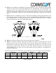
7. Notice: Observe all additional rules or restrictions regarding mounting that depend on the
type of Remote Unit. For details refer to section 7.2.2 Mechanical Specification. Install the
unit vertically with the fan unit at the top. A maximum tilt angle of 25° from a vertical
position must be kept, as in the following illustrations:
8. Notice: A spacing of 50 mm (1.97 inch) around the unit is required.
9. Notice: To ensure sufficient airflow when mounting the unit in enclosed spaces, two lid
openings (one for the air inlet and the other for the air outlet) must be provided. Do not
block these air inlets and outlets when mounting the Remote Unit. The size of each
opening must equal at least 18 x 18 cm (> 300 cm
2
). Ensure that there is no thermal short
circuit between the air inlet and air outlet. Make sure free airflow is not deflected or
otherwise obstructed.
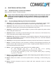
Specified torques have to be observed for certain mounting procedures according to the following table:
Type
Tallow-drop
screws
Hex nuts
Screw band
lock
Spacing
bolts
PG
(plastic)
PG
(alum.)
Thread M 4 M 8 M 4 M 8 PG 13.5 PG 29
Specified
torques
3.3 N-m 27 N-m 6 N-m 2.3 N-m 27 N-m 3.75 N-m 10 N-m
Specified torques