
User's Manual


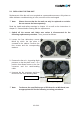
Table Of Contents
- 1.1. USED ABBREVIATIONS
- 1.2. HEALTH AND SAFETY WARNINGS
- 1.3. ABOUT COMMSCOPE SOLUTIONS
- 1.4. INTERNATIONAL CONTACT ADDRESSES FOR CUSTOMER SUPPORT
- 2. INTRODUCTION
- 3. 3. COMMISSIONING
- 4. ALARMS
- 5. MAINTENANCE
- 6. APPENDIX
- 7. INDEX

36 of 46
Status LED Indication Alarms Possible on-site measures
Alarms directly related to RU:
Power 28 V
Change power supply (RUs with door).
Replace the affected remote unit.
Temperature
Reduce environmental temperature.
Eliminate thermal short circuit.
Fan
Disconnect and connect mains. Fans
should run. If not, replace the fans at
RU.
I²C Disconnect and connect mains.
Optical alarm Tx -
Red
A
mplifier “Power
Down”
(MU: Change amplifier setting at MU
controller).
Status LED off Mains
Check power switch inside of RU (RUs
with door).
Check mains cabling.
Check mains power.
table 4-1 Status LED alarms
V1651A2
clear
Alarm LED
Alarm transmit
Alarm cause
raise
> 5 s
< 5 s
raise
> 5 s
clear
figure 4-1 Alarm triggering
For the position of the status LED see chapter 3.2.2 Connections.
Explicit troubleshooting is available in the MU software, (software manual or WEB
Interface).