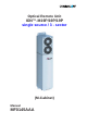
Optical Remote Unit ION™-M19P/19P/19P single source / 3 - sector (M-Cabinet) Manual MF0145AAA
© Copyright 2012 CommScope, Inc. All rights reserved. All information contained in this manual has been revised thoroughly. Yet CommScope accepts no liability for any omissions or faults. CommScope reserves the right to change all hardware and software characteristics without notice. Names of products mentioned herein are used for identification purposes only and may be trademarks and / or registered trademarks of their respective companies.
TABLE OF CONTENTS 1.1. USED ABBREVIATIONS 6 1.2. HEALTH AND SAFETY WARNINGS 7 1.3. ABOUT COMMSCOPE SOLUTIONS 10 1.4. INTERNATIONAL CONTACT ADDRESSES FOR CUSTOMER SUPPORT 11 2. INTRODUCTION 14 2.1. PURPOSE 14 2.2. 2.2.1. 2.2.2. THE ION – M 19P/19P/19P SINGLE SOURCE / 3-SECTOR Fan-Protection Kit Accessories 14 15 15 3. 3. COMMISSIONING 16 3.1. 3.1.1. 3.1.2. 3.1.3. 3.1.4.
5. MAINTENANCE 39 5.1. GENERAL 39 5.2. REPLACING THE FAN UNIT 40 5.3. CLEANING THE HEAT SINK 42 6. APPENDIX 43 6.1. ILLUSTRATIONS 43 6.2. ELECTRICAL SPECIFICATIONS 44 6.3. ENVIRONMENTAL AND SAFETY SPECIFICATIONS 44 6.4. MECHANICAL SPECIFICATIONS 44 6.5. SPARE PARTS 45 7.
FIGURES AND TABLES figure 3-1 Wall mounting........................................................................................... 18 figure 3-2 Pole-mounting kit...................................................................................... 19 figure 3-3 Pole mounting .......................................................................................... 20 figure 3-4 Mounting procedure for fan protection......................................................
General 1.1.
1.2. HEALTH AND SAFETY WARNINGS 1. Only suitably qualified personnel are allowed to work on this unit and only after becoming familiar with all safety notices, installation, operation and maintenance procedures contained in this manual. 2. Read and obey all the warning labels attached to the unit. Make sure that the warning labels are kept in a legible condition and replace any missing or damaged labels. 3.
. Note for a Class A digital device or peripheral: This equipment has been tested and found to comply with the limits for a Class A digital device, pursuant to part 15 of the FCC Rules. These limits are designed to provide reasonable protection against harmful interference when the equipment is operated in a commercial environment.
Equipment Symbols Used Please observe the meanings of the following symbols used in our equipment: Symbol Compliance Meaning --- Alert sign to R&TTE Symbol Indicates conformity with the R&TTE directive 1999/5/EC certified by the notified body no. 0700.
1.3. ABOUT COMMSCOPE SOLUTIONS CommScope is the foremost supplier of one-stop, end-to-end radio frequency (RF) solutions. Part of the CommScope portfolio are complete solutions for wireless infrastructure from top-of-the-tower base station antennas to cable systems and cabinets, RF site solutions, signal distribution, and network optimization. CommScope has global engineering and manufacturing facilities. In addition, it maintains field engineering offices throughout the world.
1.4. INTERNATIONAL CONTACT ADDRESSES FOR CUSTOMER SUPPORT Americas: Canada United States CommScope Canada Andrew LLC, A CommScope Company Mail 505 Consumers Road, Suite 803 Toronto M2J 4V8 Canada Mail 620 North Greenfield Parkway Garner, NC 27529 U.S.A. Phone +1-905-878-3457 (Office) +1-416-721-5058 (Cell) Phone +1-888-297-6433 Fax +1-905-878-3297 Fax +1-919-329-8950 E-mail Peter.Masih@commScope.com, wisupport.us@commScope.com E-mail wisupport.us@commScope.
Europe: United Kingdom Scandinavia Andrew Wireless Systems UK Ltd Andrew Norway (AMNW) Mail Unit 15, Ilex Building Mulberry Business Park Fishponds Road Wokingham Berkshire RG41 2GY England Mail P.O. Box 3066 Osloveien 10 Hoenefoss 3501 Norway Phone +44-1189-366-792 Phone + 47 32-12-3530 Fax +44-1189-366-773 Fax + 47 32-12-3531 E-mail wisupport.uk@commScope.com E-mail wisupport@commScope.
Czech Republic CommScope Solutions Czech Republic C-Com, spol. s r.o Mail U Moruší 888 53006 Pardubice Czech Republic Phone +49 871 9659171 (Office) +49 171 4001166 (Mobile) Fax +49 871 9659172 E-mail wisupport@commScope.com Africa & Middle East: Middle East & North Africa South Africa CommScope Solutions International Inc.
2. INTRODUCTION 2.1. PURPOSE Cellular telephone systems transmit signals in two directions between base transceiver station (BTS) and mobile stations (MS) within the signal coverage area. If weak signal transmissions occur within the coverage area because of indoor applications, topological conditions or distance from the transmitter, extension of the transmission range can be achieved by means of an optical distribution system. Such a system contains an optical Master Unit and several Remote Units.
provide homogeneous coverage. The compact, mechanical design is specifically architected to mount inside of or on poles and along side structures in such a way that it has a minimal visual impact. It has been specifically tested and optimized for CDMA2000, EV-DO, WCDMA and LTE. Furthermore it is provisioned for future improvements to the modulation and frequency bands. The ION-M19P/19P/19P can be easily set-up and supervised via a graphical user interface (GUI).
3. 3. COMMISSIONING 3.1. MECHANICAL INSTALLATION 3.1.1. General Read the health and safety warnings in chapter 1.2. 1. Do not install the unit in a way or at a place where the specifications outlined in the Environmental and Safety Specifications leaflet of the supplier are not met. 2. It is recommended only to use the mounting hardware delivered by the supplier. If different mounting hardware is used, the specifications for stationary use of the Remote Unit must not be exceeded.
8. To ensure sufficient airflow when mounting the unit in enclosed spaces, two lid openings (one for the air inlet and the other for the air outlet) have to be provided. Do not block these air inlets and outlets when mounting the Remote Unit. The size of each opening must equal at least 12 x 12 cm (144 cm2). Make sure, too, there is no thermal short circuit between the air inlet and air outlet.
3.1.2. Wall-Mounting Procedure Check the suitability of the wall-mounting kit and the wall. Mark the position of the drilling holes (for measurements refer to figure 3-1 Wall mounting). Drill four holes at the marked positions and insert dowels*. Use a cap nut or lock nut to screw the four dowel screws into the dowels and put the distance tubes over the screws. Hang the mounting brackets of the remote unit into the screws, and fasten them immediately using the washers and nuts.
3.1.3. Pole-Mounting Procedure Standard mounting hardware cannot be used to mount the remote unit to a pole, a column or other similar structures. Additional hardware must be used for this type of installation. Such a pole-mounting kit could include two threaded rods M8, two U-beams and mounting material like bolts and nuts.
Nut M8 DIN 934 Optical remote unit figure 3-3 Pole mounting 20 of 46
3.1.4. Mounting of Fan Protection Since the fan protection is required for the outdoor usage of a stand-alone remote unit, the mounting of this optional equipment is also described in this manual. To install the protective cover of the fan protection kit, first unscrew the four screws with the respective lock washers from the cover of the air inlet of the remote unit, and instead, screw in the four spacing bolts M4.0x30 with the four lock washers M4.0 DIN125 that are part of the fan protection kit.
3.2. ELECTRICAL INSTALLATION 3.2.1. General Read the health and safety warnings in chapter 1.2. 1. This unit contains dangerous voltages. Loss of life, severe personal injury or property damage can be the result if the instructions contained in this manual are not followed. 2. It is compulsory to ground the unit before connecting power supply. A grounding bolt is provided on the cabinet to connect the ground-bonding cable. 3.
3.2.2.
Control Connector RS232 - Local Interface This 8-pin male connector (type: Binder Series 712) is primarily to support local control of the remote unit via RS232 ASCII interface. PIN 1 2 3 4 5 6 7 8 figure 3-6 RS232 connector Assignment Not connected (n.c.) RS232 Rx RS232 Tx n.c. GND (RS232) n.c. n.c. n.c. table 3-2 RS232 connector, pin assignment 3.2.3. Grounding Grounding must be carried out.
3.2.4. Connection of the Antenna Cables The remote unit has N-type antenna connectors. For its location please refer to chapter 3.2.2 Connections. For mounting the cable connectors, it is recommended to refer to the corresponding documentation of the connector manufacturer. The bending radius of the antenna cables must remain within the given specifications.
3.2.5. Power Connection Before connecting electrical power to the units, the system must be grounded as described in the previous chapter. Mains power must be connected at the mains connector of the unit (see chapter 3.2.2 Connections). The power supply plug is part of the delivery. The correct wiring of the power supply plug is as follows: figure 3-9 AC mains plug figure 3-10 DC mains plug For the AC power supply connection, a minimum cross section of 1.
3.3. OPTICAL-FIBRE-CABLE CONNECTION - RULES Optical signals are transmitted by use of optical fibres. When connecting these fibres observe the following instructions. Note: Care should be taken when connecting and disconnecting fibreoptic cables. Scratches and dust significantly affect system performance and may permanently damage the connector. Always use protective caps on fibre-optic connectors not in use. In general, optical fibres do not need special protective measures.
Remove fibre-optic protective caps. Do not bend the fibre-optic cable in a tight radius (< 4 cm) as this may cause cable damage and interrupt transmission. Using high-grade alcohol and lint-free cotton cleaning swabs, clean the end of the fibre-optic cable that will be inserted in the optical connectors on the donor interface box. Blow out the laser receptacle with clean and dry compressed air to remove any particulate matter.
For plug assembly, observe the following instruction: 1. Pass one or two contacts through the backshell and the clamp ring. 2. Place the contact(s) on the lower insulation body by pushing the groove of the contact into the cavity. If there is only one contact, cavity A must be used. * 3. Then, mount the upper insulation body on the lower insulation body. ** Upper insulation body Cavity B Cavity A 4. Bring the insulator into the plug.
7. Bring the plastic ring over the cable(s), push it into the backshell and compress the seals and plastic ring by screwing the clamp ring tight (no gap) using a spanner with opening 20. *** Screw tight until gap is closed 8. Connect the plug to the optical-fibre 9. To lock the connector, push the black connector of the remote unit, again by locking ring forward.**** fitting a stamp on the plug into the groove of the connector.
prot ect ive plug f ibre cable plast ic ring reducer Screw t he reducer t o t he prot ect ive plug backshell wit hout gap. coupling Place t he appropriat e seal part s (wit h) one groove f or one cont act or t wo grooves f or t wo cont act s) over t he cable(s) and push t hem int o t he backshell. prot ect ive t ube Push the fibre-optic cable carefully through the tube until it comes out at the other end.
3.4. COMMISSIONING Read the health and safety warnings in chapter 3.4 Commissioning as well as the description carefully to avoid mistakes and proceed step by step as described! Do not operate the remote unit without terminating the antenna connectors. The antenna connectors may be terminated by connecting them to their respective antennas or to a dummy load.
Commissioning an ION-M Remote Unit Manual for Remote Unit Philips screwdriver Mounting kit Spanner, size 13 mm Drilling machine Dowels Screw driver Screw driver Spanner, size 13 mm Start Preperation Unpack RU, RU accessories and mounting kit. Mechanical installation Fasten wall or pole mounting kit to wall or pole. Mechanical installation Mount RU to mounting kit, ensure suffient air flow and avoid thermal short circuits.
LED on? No Check power switch inside RU (RUs with door). Check mains cabling. Check mains power. Yes LED status Red Internal Error Change power supply (RUs with a door). Reduce environmental temperature. Eliminate thermal short circuit. Disconnect and connect mains. Fans should run. If not, replace the fans at RU. MU: Change amplifier setting at MU controller Orange Yellow LED status Red Green Spare RU available? External error Close the door (RUs with a door). Check externally connected devices.
4. ALARMS 4.1. BITE AND ALARMS The Built-In Test concept comprises the monitoring of the power supplies, the power amplifiers and the optical interface. All occurring alarms can be checked via software at the master unit. 4.2. HANDLING OF ALARMS As soon as the software acknowledges a valid alarm, a message is transmitted to the master unit. If the reason for the alarm has been cleared or if the alarm should continue, a new alarm message will not be repeated.
Status LED Indication Red Status LED off Alarms Possible on-site measures Alarms directly related to RU: Change power supply (RUs with door). Power 28 V Replace the affected remote unit. Reduce environmental temperature. Temperature Eliminate thermal short circuit. Disconnect and connect mains. Fans Fan should run. If not, replace the fans at RU. I²C Disconnect and connect mains. Optical alarm Tx Amplifier “Power (MU: Change amplifier setting at MU Down” controller).
4.5. EXTERNAL ALARM INPUTS AND OUTPUTS G1038Z0 G1038Z0 figure 4-2 Flange connector, 5 poles figure 4-3 Flange connector, 7 poles The alarm outputs (open collector output 5 V / 1 mA) are normally low. In case of an alarm they are high active (5 V). They can be used to monitor alarms with an external alarm indicator. The +28 V pin (for its location see figure 4-3 Flange connector, 7 poles) is protected by a 500 mA thermoswitch.
With the external alarm inputs, it is possible to monitor the status of connected devices, e.g. a UPS, via software. All alarm inputs are normally high (5 V) without connection. The polarity (high/ low) can be set via the software at the Master Unit (for details please see according software manual). The device to be monitored must be connected so that the alarm contacts will be closed in case of an alarm (I max = 8 mA). The alarm inputs are potential-free with common ground.
5. MAINTENANCE 5.1. GENERAL Read the health and safety warnings in chapter 1.2. Note: The remote unit does not require preventative maintenance measures. Note: To prevent malfunctions of the cooling system due to dirt or pollution, it is recommended to clean the heat sink at regular intervals. These cleaning intervals depend mainly on the location of the remote unit and the corresponding degree of pollution.
5.2. REPLACING THE FAN UNIT Replacement of the fan unit is not required as a preventative measure. Only when an alarm indicates a malfunctioning of a fan, must the unit be exchanged. Note: Please observe that the fan unit can only be replaced as a whole. Do not remove the fans separately. Read the health and safety warnings in chapter 1.2 as well as the instructions in chapter 5.1 General before starting with the replacement. 1. Switch off the remote unit.
5. To mount the new fan unit, re-connect the earth-bonding cable and the fan connector (see step 4). Then, place the fan unit back into its original position and fix it tight as shown below: 6. Screw the whole fan unit to the cabinet with the four tallow-drop screws M4x8 (see step 2). In order not to exceed the specified torque of 330 Ncm, use an appropriate tool.
5.3. CLEANING THE HEAT SINK Note: Read the health and safety warnings in chapter 1.2 as well as the instructions in chapter 5.1 General before starting with the replacement procedure. Then, proceed as follows: 1. Switch off the remote unit. Make sure that mains is disconnected for the following procedure. 2. Remove the fan plate with the fan unit 3. Use compressed air (max. 5 bar) to from the remote unit as described in blow out the heat sink from back to chapter 5.
6. APPENDIX 6.1.
6.2. ELECTRICAL SPECIFICATIONS ION-M19P/19P/19P Electrical 85 Vac to 264 Vac Mains power 115 Vac or 230 Vac Power Supply Power consumption 770 watts Optical Connectors E2000/APC 8° Optical return loss 45 dB minimum Fiber type Single mode E9/125 mm Optical link budget 0 dB to 10 dB 6.3. ENVIRONMENTAL AND SAFETY SPECIFICATIONS Note: For detailed information, please refer to the Environmental and Safety Specifications leaflet of the supplier, related to ETS 300 019 (European Telecommunication Standard).
6.5. SPARE PARTS The following list contains all parts available for the Remote Unit. The configuration of the delivered unit meets the requirements of the customer and can differ depending on the state of the delivery. Maintenance of the ION-M19P/19P/19P should be performed on an FRU (Field Replaceable Unit) basis only. Do not damage the warranty labels on the components, as this voids the warranty.
7. INDEX A H Abbreviations.......................................................... 6 Alarms Alarm Status .................................................... 35 Bite and Alarms ............................................... 35 External Inputs........................................... 37, 38 Handling of Alarms .......................................... 35 List ................................................................... 38 Outputs ......................................................