
Installation Instruction

6. Notice: A spacing of 40 mm (1.58 inch) around the unit is required.
7. Notice: To ensure sufficient airflow when mounting the unit in enclosed spaces, two lid
openings (one for the air inlet and the other for the air outlet) must be provided. Do not
block these air inlets and outlets when mounting the Remote Unit. The size of each
opening must equal at least 16 x 16 cm (>250 cm
2
). Ensure that there is no thermal short
circuit between the air inlet and air outlet. Make sure free airflow is not deflected or
otherwise obstructed.
8. Notice: Depending on the installation type (wall or pole), the corresponding mounting kits
must be ordered from the manufacturer. If any different or additional mounting material is
used, ensure that the mounting remains as safe as the mounting designed by the
manufacturer. The specifications for stationary use of the Remote Unit must not be
exceeded. Ensure that the static and dynamic strengths are adequate for the
environmental conditions of the site. The mounting itself must not vibrate, swing or move in
any way that might cause damage to the Remote Unit.
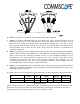
9. Notice: To avoid damage when mounting the unit, always make sure that the M8 washers
(DIN9021 or DIN125 depending on the mounting kit) are placed behind and in front of the
mounting drillings of the unit.
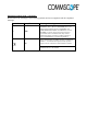
Specified torques have to be observed for certain mounting procedures according to the following table:
Type
Tallow-drop
screws
Hex
nuts
Spacing
bolts
PG
(plastic)
PG
(aluminium)
Thread
M 4 M 8 M 4 M 8 PG 13.5 PG 29
Specified torques
3.3 N-m 27 N-m 2.3 N-m 27 N-m 3.75 N-m 10 N-m
Specified torques
The mounting procedures for a stand-alone Remote Unit without optional accessories are described and
illustrated in the following sections. For further information regarding special mounting procedures
including mounting of accessory equipment, please see separate manual.