
User's Manual


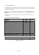
Table Of Contents
- 1. GENERAL
- 2. INTRODUCTION
- 3. COMMISSIONING
- 4. ALARMS
- 5. MAINTENANCE
- 6. SPECIFICATIONS
- 7. INDEX
- 8. LIST OF CHANGES

The alarm outputs are potential-free.
They can be used to monitor alarms with
an external alarm indicator. Devices
connected to these outputs must not
exceed a maximum switching power of
28 Vdc, 0.5 A. For the location of the
connecting clamps of the alarm outputs
see figure above.
Clamp 2
Clamp 1
Clamp 3
figure 4-3 Alarm-output contacts, alarm condition
4.6. REDUNDANCY RELAY CONFIGURATION
Main Unit
Substitute Unit
Combining Unit
UL
DL
AC/DC cable, 1.2 m IP67
side labelled "MAIN"
AC/DC cable, 1.2m IP67
side labelled "Subsitute"
G1131M4
figure 4-4 Redundancy connection, cabling
Note: The Combining Unit illustrated above is not part of this delivery.
Redundancy Relay – Description
figure 4-5 Redundancy RF relay figure 4-6 Redundancy connectors,
Main Unit and Substitute Unit
Exterior
connectors &
cables
Cables in
Connector flange
interior cabinet
RF relay
33 of 42