
User's Manual


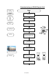


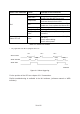
Table Of Contents
- 1. GENERAL
- 2. INTRODUCTION
- 3. COMMISSIONING
- 4. ALARMS
- 5. MAINTENANCE
- 6. SPECIFICATIONS
- 7. INDEX
- 8. LIST OF CHANGES

Status LED indication Alarms Possible on-site measures
Alarms directly related to RU:
Power 28 V
Change power supply (RUs with door).
Replace the affected remote unit.
Temperature
Reduce environmental temperature.
Eliminate thermal short circuit.
Fan *
Disconnect and connect mains. Fans
should run. If not, replace the fans at RU.
I²C Disconnect and connect mains.
Optical alarm Tx Exchange RU.
Red
A
mplifier “Power
Down”
(MU: Change amplifier setting at MU
controller).
Status LED off Mains
Check power switch inside of RU (RUs
with door).
Check mains cabling.
Check mains power.
table 4-1 Status LED alarms
* only applicable if the RU is equipped with a fan
V1651A2
clear
Alarm LED
Alarm transmit
Alarm cause
raise
> 5 s
< 5 s
raise
> 5 s
clear
figure 4-1 Alarm triggering
For the position of the LED see chapter 3.2.2 Connections.
Explic
it troubleshooting is available in the MU software, (software manual or WEB
Interface).
30 of 42