Optical Remote Unit ION™- M80/90/19P (M-Cabinet) User's Manual MF0133ABA
User’s Manual for Remote Unit ION™-M80/90/19P © Copyright 2011 CommScope, Inc. All rights reserved. Andrew Solutions is a trademark of CommScope, Inc. All information contained in this manual has been revised thoroughly. Yet Andrew Solutions accepts no liability for any omissions or faults. Andrew Solutions reserves the right to change all hard- and software characteristics without notice.
TABLE OF CONTENTS 1. GENERAL 5 1.1. USED ABBREVIATIONS 5 1.2. HEALTH AND SAFETY WARNINGS 6 1.3. ABOUT ANDREW SOLUTIONS 8 1.4. INTERNATIONAL CONTACT ADDRESSES FOR CUSTOMER SUPPORT 9 2. FUNCTIONAL DESCRIPTION 11 2.1. PURPOSE 11 2.2. THE ION-M80/90/19P 11 2.3. 2.3.1. 2.3.2. COMPONENTS OF THE ION-M80/90/19P REMOTE UNIT Fan-Protection Kit Accessories 12 12 12 3. COMMISSIONING 13 3.1. 3.1.1. 3.1.2. 3.1.3. 3.1.4.
User’s Manual for Remote Unit ION™-M80/90/19P 5. MAINTENANCE 37 5.1. GENERAL 37 5.2. REPLACING THE FAN UNIT 38 5.3. CLEANING THE HEAT SINK 40 6. APPENDIX 41 6.1. ILLUSTRATIONS 41 6.2. 6.2.1. 6.2.2. 6.2.3. SPECIFICATIONS Electrical Specifications Environmental and Safety Specifications Mechanical Specifications 42 42 42 42 6.3. SPARE PARTS 43 7. INDEX 44 FIGURES AND TABLES figure 3-1 Wall mounting........................................................................................
1 General 1. GENERAL 1.1.
User’s Manual for Remote Unit ION™-M80/90/19P 1.2. HEALTH AND SAFETY WARNINGS 1. Only suitably qualified personnel is allowed to work on this unit and only after becoming familiar with all safety notices, installation, operation and maintenance procedures contained in this manual. 2. Read and obey all the warning labels attached to the unit. Make sure that the warning labels are kept in a legible condition and replace any missing or damaged labels. 3.
1 General 12. Before opening the unit, disconnect mains. 13. ESD precautions must be observed! Before commencing maintenance work, use the available grounding system to connect ESD protection measures. 14. This unit complies with European standard EN60950. 15. Make sure the repeater settings are according to the intended use (see also product information of manufacturer) and regulatory requirements are met. 16.
User’s Manual for Remote Unit ION™-M80/90/19P 1.3. ABOUT ANDREW SOLUTIONS Andrew Wireless Systems GmbH based in Buchdorf/ Germany, is a leading manufacturer of coverage equipment for mobile radio networks, specializing in high performance, RF and optical repeaters. Our optical distributed networks and RF repeater systems provide coverage for every application: outdoor use, indoor installations, tunnels, subways and many more.
1 General 1.4. INTERNATIONAL CONTACT ADDRESSES FOR CUSTOMER SUPPORT Americas: Canada United States Andrew Solutions Canada Andrew Solutions, Andrew LLC, A CommScope Company Mail 620 North Greenfield Parkway Garner, NC 27529 U.S.A. Mail 620 North Greenfield Parkway Garner, NC 27529 U.S.A. Phone +1-905-878-3457 (Office) +1-416-721-5058 (Mobile) Phone +1-888-297-6433 Fax +1-905-878-3297 Fax +1-919-329-8950 E-mail Peter.Masih@commscope.com, WIsupport.us@commscope.com E-mail WIsupport.
User’s Manual for Remote Unit ION™-M80/90/19P Europe: United Kingdom France Andrew Solutions UK Ltd CommScope France Mail Unit 15, Ilex Building Mulberry Business Park Fishponds Road Wokingham Berkshire RG41 2GY England Mail Immeuble Le Lavoisier 4, Place des Vosges 92052 Courbevoie France Phone +44-1189-366-792 Phone +33-1 82 97 04 00 Fax +44-1189-366-773 Fax +33-1 47 89 45 25 E-mail WIsupport.uk@commscope.com E-mail WIsupport@commscope.
2 Functional Description 2. FUNCTIONAL DESCRIPTION 2.1. PURPOSE Cellular telephone systems transmit signals in two directions between base transceiver station (BTS) and mobile stations (MS) within the signal coverage area. If weak signal transmissions occur within the coverage area because of indoor applications, topological conditions or distance from the transmitter, extension of the transmission range can be achieved by means of an optical distribution system.
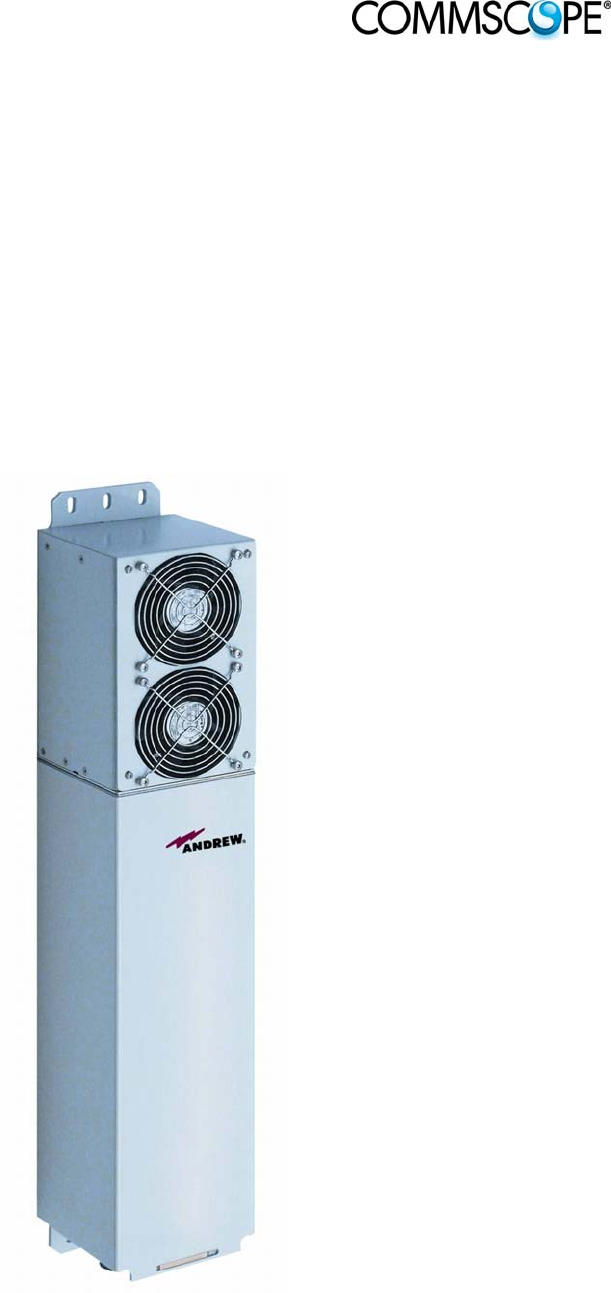
User’s Manual for Remote Unit ION™-M80/90/19P 2.3. COMPONENTS OF THE ION-M80/90/19P REMOTE UNIT 2.3.1. Fan-Protection Kit In order to protect the fan unit (e.g. against rain), a protective cover to be mounted over the air inlet is delivered with the unit. For more details see chapter 3.1.4 Mounting of Fan Protection. Mounting of the fan-protection kit is only mandatory for outdoor applications, however, not mandatory for indoor applications. 2.3.2.
3 Commissioning 3. COMMISSIONING 3.1. MECHANICAL INSTALLATION 3.1.1. General Read the health and safety warnings in chapter 1.2. 1. Do not install the unit in a way or at a place where the specifications outlined in the Environmental and Safety Specifications leaflet of the supplier are not met. 2. It is recommended only to use the mounting hardware delivered by the supplier. If different mounting hardware is used, the specifications for stationary use of the Remote Unit must not be exceeded.
User’s Manual for Remote Unit ION™-M80/90/19P 7. A spacing of 40 mm (1.58 inch) around the unit is required. 8. To ensure sufficient airflow when mounting the unit in enclosed spaces, two lid openings (one for the air inlet and the other for the air outlet) have to be provided. Do not block these air inlets and outlets when mounting the Remote Unit. The size of each opening must equal at least 17 x 17 cm (290 cm2). Make sure, too, there is no thermal short circuit between the air inlet and air outlet.
3 Commissioning 3.1.2. Wall-Mounting Procedure Check the suitability of the wall-mounting kit and the wall. Mark the position of the drilling holes (for measurements refer to figure 3-1 Wall mounting). Drill four holes at the marked positions and insert dowels *. Use a cap nut or lock nut to screw the four dowel screws into the dowels and put the distance tubes over the screws. Hang the mounting brackets of the Remote Unit into the screws, and fasten them immediately using the washers and nuts.
User’s Manual for Remote Unit ION™-M80/90/19P 3.1.3. Pole-Mounting Procedure Standard mounting hardware cannot be used to mount the Remote Unit to a pole, a column or other similar structures. Additional hardware must be used for this type of installation. Such a pole-mounting kit could include two threaded rods M8, two U-beams and mounting material like bolts and nuts.
3 Commissioning TESPA screw band, stainless, 11 mm Optical Remote Unit Washer DIN 125 Form B Ø 8.0 Lock washer for M8.
User’s Manual for Remote Unit ION™-M80/90/19P 3.1.4. Mounting of Fan Protection Since the fan protection is required for the outdoor usage of a stand-alone Remote Unit, the mounting of this optional equipment is also described in this manual. To install the protective cover of the fan protection kit, first unscrew the four screws with the respective lock washers from the cover of the air inlet of the Remote Unit, and instead, screw in the four spacing bolts M4.0x30 with the four lock washers M4.
3 Commissioning 3.2. ELECTRICAL INSTALLATION 3.2.1. General Read the health and safety warnings in chapter 1.2. 1. This unit contains dangerous voltages. Loss of life, severe personal injury or property damage can be the result if the instructions contained in this manual are not followed. 2. Ground the unit before connecting power supply. A grounding bolt is provided on the cabinet to connect the ground-bonding cable. 3.
User’s Manual for Remote Unit ION™-M80/90/19P 12. The unit complies with the surge requirement according to EN 61000-4-5 (fine protection); however, it is recommended to install an additional medium (via local supply connection) and/or coarse protection (external surge protection), depending on the individual application, in order to avoid damage caused by overcurrent. 13. Observe the labels on the front panels before connecting or disconnecting any cables. 3.2.2.
3 Commissioning 3.2.3. Grounding Grounding must be carried out. Connect an earth-bonding cable to the grounding connection provided at the outside of the Remote Unit (see chapter 3.2.2 Connections). Do not use the grounding connection to connect external devices. figure 3-6 Grounding bolt with loosened hex nut figure 3-7 Grounding bolt, schematic view After loosening the hex nut, connect the earth-bonding cable between the two washers as illustrated in the figures above.
User’s Manual for Remote Unit ION™-M80/90/19P 3.2.4. Power Connection Before connecting electrical power to the units, the system must be grounded as described in the previous chapter. Mains power must be connected at the mains connector of the unit (see chapter 3.2.2 Connections). The power supply plug is part of the delivery. The correct wiring of the power supply plug is as follows: figure 3-8 AC mains plug figure 3-9 DC mains plug For the AC power supply connection, a minimum cross section of 1.
3 Commissioning 3.3. CONNECTION OF THE ANTENNA CABLES The Remote Unit has N-type antenna connectors. For its location please refer to chapter 3.2.2 Connections. For mounting the cable connectors, it is recommended to refer to the corresponding documentation of the connector manufacturer. The bending radius of the antenna cables must remain within the given specifications.
User’s Manual for Remote Unit ION™-M80/90/19P System attenuation and attenuation of optical components must be determined. This can be achieved by measuring attenuation and reflection with an appropriate measuring instrument. For pigtails, a total value of < 0.4 dB (measured to a reference plug) can be assumed due to the dead zone of the reflectometer. These measurements must be made with a sufficient length of optical fiber, at the input and output of the device which has to be measured.
3 Commissioning Cleaning Procedure for Fiber-Optical Components: Any contamination in the fiber connection results in additional optical transmission loss which could cause whole system failure. It is thus recommended that every fiber connector be inspected and cleaned prior to mating. The goal is to eliminate any dust or contamination and to provide a clean environment for the fiber-optic connection. When you clean fiber components, always complete the following steps carefully: 1.
User’s Manual for Remote Unit ION™-M80/90/19P 3.4.1. Protective Plug Connection: A protective plug is provided for the connection of the fibre-optic cables. figure 3-10 Protective-plug assembly ) Note: Page 26 Only high-quality connectors must be used for this type of plug. Qualified brands are Diamond or Huber & Suhner. MF0133ABA.
3 Commissioning For plug assembly, observe the following instruction: 1. Pass one or two contacts through the backshell and the clamp ring. 2. Place the contact(s) on the lower insulation body by pushing the groove of the contact into the cavity. If there is only one contact, cavity A must be used. * 3. Then, mount the upper insulation body on the lower insulation body. ** Upper insulation body Cavity B Cavity A 4. Bring the insulator into the plug.
User’s Manual for Remote Unit ION™-M80/90/19P 7. Bring the plastic ring over the cable(s), push it into the backshell and compress the seals and plastic ring by screwing the clamp ring tight (no gap) using a spanner with opening 20. *** Screw tight until gap is closed 8. Connect the plug to the optical-fibre 9. To lock the connector, push the black connector of the Remote Unit, again locking ring forward.**** by fitting a stamp on the plug into the groove of the connector.
3 Commissioning Protective plug Fiber cable Ring 3/4 Reducer Screw the reducer to the protective plug backshell without any gap! Coupling Place the appropriate seal parts (with) one groove for one contact or two grooves for two contacts) over the cable(s) and push them into the backshell! Protective tube Push the fiber-optic cable carefully through the tube until it comes out at the other end.
User’s Manual for Remote Unit ION™-M80/90/19P 3.5. COMMISSIONING Read the health and safety warnings in chapter 1.2 as well as the description carefully to avoid mistakes and proceed step by step as described! Do not operate the Remote Unit without terminating the antenna connectors. The antenna connectors may be terminated by connecting them to their respective antennas or to a dummy load.
3 Commissioning Commissioning an ION-M Remote Unit Manual for Remote Unit Philips screwdriver Mounting kit Spanner, size 13 mm Drilling machine Dowels Screw driver Screw driver Spanner, size 13 mm Start Preperation Unpack RU, RU accessories and mounting kit. Mechanical installation Fasten wall or pole mounting kit to wall or pole. Mechanical installation Mount RU to mounting kit, ensure suffient air flow and avoid thermal short circuits.
User’s Manual for Remote Unit ION™-M80/90/19P LED on? No Check power switch inside RU (RUs with door). Check mains cabling. Check mains power. Yes LED status Red Internal Error Change power supply (RUs with a door). Reduce environmental temperature. Eliminate thermal short circuit. Disconnect and connect mains. Fans should run. If not, replace the fans at RU.
4 Alarms 4. ALARMS 4.1. BITE AND ALARMS The Built-In Test concept comprises the monitoring of the power supplies, the power amplifiers and the optical interface. All occurring alarms can be checked via software at the Master Unit. 4.2. HANDLING OF ALARMS As soon as the software acknowledges a valid alarm, a message is transmitted to the Master Unit. If the reason for the alarm has been cleared or if the alarm should continue, a new alarm message will not be repeated.
User’s Manual for Remote Unit ION™-M80/90/19P Red Status LED off Alarms directly related to RU: Change power supply (RUs with door). Power 28 V Replace the affected remote unit. Reduce environmental temperature. Temperature Eliminate thermal short circuit. Disconnect and connect mains. Fans Fan should run. If not, replace the fans at RU. I²C Disconnect and connect mains. Optical alarm Tx Exchange RU. Amplifier “Power (MU: Change amplifier setting at MU Down” controller).
4 Alarms 4.5. EXTERNAL ALARM INPUTS AND OUTPUTS G1038Z0 figure 4-1 Flange connector, 5 poles G1038Z0 figure 4-2 Flange connector, 7 poles The alarm outputs (open collector output 5 V / 1 mA) are normally low. In case of an alarm they are high active (5 V). They can be used to monitor alarms with an external alarm indicator. The +28 V pin (for its location see figure 4-2 Flange connector, 7 poles) is protected by a 500 mA thermoswitch.
User’s Manual for Remote Unit ION™-M80/90/19P With the external alarm inputs it is possible to monitor the status of connected devices, e.g. a UPS, via software. All alarm inputs are normally high (5 V) without connection. The polarity (high/ low) can be set via the software at the Master Unit (for details please see according software manual). The device to be monitored must be connected so that the alarm contacts will be closed in case of an alarm (I max = 8 mA).
5 Maintenance 5. MAINTENANCE 5.1. GENERAL Read the health and safety warnings in chapter 1.2. ) Note: The Remote Unit does not require preventative maintenance measures. ) Note: To prevent malfunctions of the cooling system due to dirt or pollution, it is recommended to clean the heat sink at regular intervals. These cleaning intervals depend mainly on the location of the Remote Unit and the corresponding degree of pollution.
User’s Manual for Remote Unit ION™-M80/90/19P 5.2. REPLACING THE FAN UNIT Replacement of the fan unit is not required as a preventative measure. Only if an alarm indicates a malfunctioning of a fan must the unit be exchanged. ) Note: Please observe that the fan unit can only be replaced as a whole. Do not remove the fans separately. Read the health and safety warnings in chapter 1.2 as well as the instructions in chapter 5.1 General before starting with the replacement. 1. Switch off the Remote Unit.
5 Maintenance 5. To mount the new fan unit, re-connect the earth-bonding cable and the fan connector (see step 4). Then, place the fan unit back into its original position and fasten it tight as shown below: 6. Screw the whole fan unit to the cabinet with the four tallow-drop screws M4x8 (see step 2). In order not to exceed the specified torque of 330 Ncm, use an appropriate tool.
User’s Manual for Remote Unit ION™-M80/90/19P 5.3. CLEANING THE HEAT SINK ) Note: Read the health and safety warnings in chapter 1.2 as well as the instructions in chapter 5.1 General before starting with the replacement procedure. Then, proceed as follows: 7. Switch off the Remote Unit. Make sure that mains is disconnected for the following procedure. 8. Remove the fan plate with the fan unit 9. Use compressed air (max.
6 Appendix 6. APPENDIX 6.1.
User’s Manual for Remote Unit ION™-M80/90/19P 6.2. SPECIFICATIONS 6.2.1. Electrical Specifications ION-M80/90/19P * Electrical Power Mains power 115 Vac or 230 Vac supply Power consumption 530 Watts Optical Connectors E2000/APC 8° Optical return loss 45 dB minimum Fiber type Single mode E9/125 mm Optical link budget 0 dB to 10 dB All figures are typical values. * An Extension Unit for 1700/2100 MHz (AWS in Extension Unit) can optionally be available. All data is subject to change without notice. 6.2.2.
6 Appendix 6.3. SPARE PARTS The following list contains all parts available for the Remote Unit. The configuration of the delivered unit meets the requirements of the customer and can differ depending on the state of the delivery. Maintenance of the ION-M80/90/19P should be performed on an FRU (Field Replaceable Unit) basis only. Do not damage the warranty labels on the components, as this voids the warranty.
User’s Manual for Remote Unit ION™-M80/90/19P 7. INDEX A I Address of Andrew Wireless Systems GmbH....... 10 Alarms Alarm Status .................................................... 33 Bite and Alarms ............................................... 33 External Inputs........................................... 35, 36 Handling of Alarms .......................................... 33 List ................................................................... 36 Outputs ..........................................