
User's Manual


6 Maintenance
Page 39
- To get access to the power amplifier (PA), the sheet by which the PA is
covered must be removed. Therefore, unscrew the four M3x6 Phillips
countersunk-head screws.
- Take out the defect plug-in module carefully at the locking device from the
front side. Use your finger for pressing down the spring inside the locking
device.
- When the PA module is exchanged, make sure the address, which can be
adjusted by means of the rotary address switch (see following illustrations) has
been set correctly according to the illustration on the labels and/ or the
following table:
PA addresses of switch positions:
Main Unit Extension Unit
800 MHz Band PA 1: 0 2
nd
400 MHz Band PA 3: 0
400 MHz Band PA 2: 1 3
rd
400 MHz Band PA 4 1
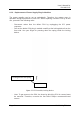
figure 6-2 Rotary address switch, location on PA
- Insert the new plug-in module until the stop by pressing down the spring of the
locking device.
- Re-connect mains by re-connecting the IEC power connector.
- Run HW discovery command on the Web interface of the Master Unit.
- Check whether the system has to be levelled again.
- Check the system gain.
Rotary address switch
Locking device