
User's Manual


User’s Manual for
ION-M4/8 19"
Page 36 M0132AVA_FCC.doc
The following table shows the coding for the status LED and possible on-site
measures that could be checked before referring to the master unit alarm list:
Status LED indication Alarms Possible on-site measures
Green
No alarm Æ
Status ok
Alarms not directly related to RU:
External alarms
Check externally connected devices.
Optical alarm Rx
Check fibre loss of optical link.
Check optical connectors.
Clean optical connectors.
(MU: Check optical output power of
corresponding OTRx at master unit).
Orange
ALC alarm
(MU: Decrease DL input power of
affected band).
Alarms directly related to RU:
Power 28 V
Change power supply.
Replace the affected remote unit.
Temperature
Reduce environmental temperature.
Eliminate thermal short circuit.
Fan
Disconnect and connect mains. Fans
should run briefly.
I²C Disconnect and connect mains.
Optical alarm Tx -
Red
A
mplifier “Power
Down”
(MU: Change amplifier setting at MU
controller).
Status LED off Mains
Check power switch.
Check mains cabling.
Check mains power.
table 5-1 Status LED alarm coding
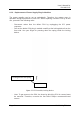
V1651A2
clear
Alarm LED
Alarm transmit
Alarm cause
raise
> 5 s
< 5 s
raise
> 5 s
figure 5-1 Alarm triggering