
User's Manual


3 Functional Description
Page 15
3. FUNCTIONAL DESCRIPTION
3.1. GENERAL
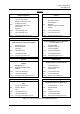
The following figure shows the configuration of an ION-M4/8 19" RU:
o
e
o
e
DL
UL
UL/DL
WDM OTRX
from / to Master Unit
Optical Module OTRx 1/4/9
RU-LS
+32 VDC
I²C
350 – 512 MHz
67 – 174 MHz
716 – 960 MHz
350 – 512 MHz
67 – 174 MHz
698 – 915 MHz
1:3
Power Amplifier 1
Fin. Ampl.
851-894 MHz
+28 VDCI²C
Power Amplifier 2
Fin.Ampl. 45W
851-894
+28 VDCI²C
Power Amplifier 3
Fin. Ampl.
450-490 MHz
+28 VDCI²C
Power Amplifier 4
Fin. Ampl.
450-490 MHz
+28 VDCI²C
Control Unit
RCM161-C LT
PSU 1
AC IN 100-240 V
Control Unit EU
RCM161-C LT
19" Alarm Board EU
with RCM
PSU 2
AC IN 100-240 V
Mains
RS485
+32 VDC
I²C
Crossband coupler
with DC bypass
Act. Combiner
With DC supply
ANT
ANT
Duplexer
DL 851-869MHz
UL 806-824MHz
Duplexer
DL 460.1625-462.9875MHz
UL 465.1625-467.9875MHz
ID 7602995-00
Duplexer
DL 470.775-471.000 MHz
UL 473.775-474.000 MHz
Duplexer
DL 483.150-483.575 MHz
UL 486.150-486.575 MHz
Ext. Al in
Ext. Al out
32V
E3189B0B
Main (I2C bus A)
Extension (I2C bus B)
I²C
0x010
(10 Bit)
„0"
I²C
figure 3-1 Configuration of an ION-M4/8 19" RU