
User's Manual


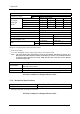


Table Of Contents

7 Appendix
Page 47
1900 MHz
UL 1850 to 1915 MHz
Frequency range
DL 1930 to 1995 MHz
Number of carriers 1 2 4 8
GSM 43 dBm 40 dBm 37 dBm 34 dBm
CDMA 43 dBm 40 dBm 37 dBm 34 dBm
UMTS 43 dBm 40 dBm 37 dBm 34 dBm
RF output
power per
carrier
2)
LTE 43 dBm 40 dBm
4)
37 dBm 34 dBm
Spurious emission <-13 dBm / 1 MHz
DL output tolerance over frequency ±1 dB
DL output tolerance over temperature ±0.5 dB
3)
ICP3 optimized NF optimized
UL Input ICP3 -12 dBm -18 dBm
UL Noise figure (NF)
5)
7 dB
11 dB max.
4.5 dB
6 dB max.
DL 40 dB 40 dB
Gain
UL 40 dB 47 dB
All figures are typical values unless otherwise stated.
3)
With active cooling
4)
For carrier bandwidth <5 MHz output power shall be decreased by 3 dB
5)
Note: The noise figure (NF) stated above refers to one Remote Unit (RU) per sector. The
NF-system increases with the number of the RUs per sector. It is recommended not
to operate above four RUs per sector. With four RUs per sector, the system NF will
be increased by 6 dB.
System Supervision and Control
Commands
RF on/off
External control ports
Alarms Summary; Power supply; Optical UL and DL failure; Temperature
Supervision
Output power on a per-channel and per-band basis (optional)
All data is subject to change without notice.
7.2.2. Mechanical Specifications
Height, width, depth * 831 x 156 x 147 mm (32.7 x 6.1 x 5.8 in)
Weight 20 kg (44 Ib)
* Spacing required 40 mm (1.58 in) around unit
All data is subject to change without notice.