
User's Manual
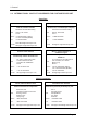
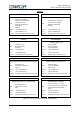
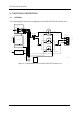


Table Of Contents

3 Functional Description
Page 15
3. FUNCTIONAL DESCRIPTION
3.1. GENERAL
The following figure shows the configuration of an ION-M17HP/19P Remote Unit.
o
e
o
e
DL
UL
UL/DL
WDM OTRX
from / to Master Unit
Optical Module
+28 VDC
I²C
Power Supply Unit AC
+28 VDC
I²C
Buffer
100..240VAC
+28 VDCI²C
Buffer
Power Amplifier
+28 VDCI²C
Buffer
2100 MHz
Power Amplifier
+28 VDCI²C
Buffer
2100 MHz
935-941MHz
728-894MHz
1805-2170MHz
896-902MHz
698-849MHz
1710-2130MHz
1900 MHz
Power Amplifier
Duplexer unit
With distribution unit
Antenna
port
Crossband coupler
(part of duplexer unit)
1930 - 1995 MHz
2110 – 2155 MHz
1710 – 1755 MHz
1850 – 1910 MHz
DC
Probe (nd)
Splitter (part of
duplexer unit)
Combiner (part
of duplexer unit)
(100 - 240 VAC)
Control Unit RCM161
X11
X3
3
3 colors LED
X12
4 external alarms
inputs
X12
4 external alarms
outputs
X12+28 VDC output
5
5
X6
Fan
2
X12RS232
3
26
Ext.- Connector
Pin 1: 700MHz DL
Pin 2: 700MHz UL
Pin 3: n.c.
Pin 4: n.c.
Pin 5: n.c.
Pin 6: RS485 +
Pin 7: RS485 -
Ext. Board
RS485
E1187B000
figure 3-1 Configuration of an ION-M17HP/19P Remote Unit