
User's Manual
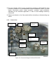
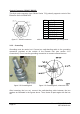
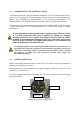
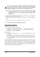
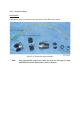
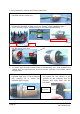
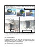
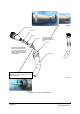
Table Of Contents

3.3. CONNECTION OF THE ANTENNA CABLES
The Remote Unit has 7/16-type antenna connectors. For its location please refer to
section 3.2.2 Connections. For mounting the cable connectors, it is recommended to
refer to the corresponding documentation of the connector manufacturer. The
bending radius of the antenna cables must remain within the given specifications.
For the selection of cable and antenna it should be considered that, on the one hand,
a cable with higher loss is less expensive but, on the other hand, it impairs
performance.
Use an appropriate torque wrench for the coupling torque (25 N-m/ 19 ft lb)
of 7-16 DIN connectors with 1-1/4 in opening to tighten the 7/16-type
antenna connectors. For example, use torque wrench of item no. 244377
available from the Andrew e-catalog. Do NOT use your hands or any other
tool (e.g. a pair of pliers)! This might cause damage to the connector and
lead to a malfunction of the Remote Unit.
To minimize passive inter-modulation (PIM) distortion, attention has to
be paid to the physical condition of the connector junctions. Do not use
connectors that show signs of corrosion on the metal surface. Prevent
the ingress of water into the connector. Attach and torque the
connectors properly.
3.4. POWER CONNECTION
Before connecting electrical power to the units, the system must be grounded as
described in the previous section.
Mains power must be connected at the power supply connector of the unit (see
section 3.2.2 Connections).
The power supply plug is part of the delivery. The correct wiring of the power supply
plug is as follows:
figure 3-10 AC power supply plug
PIN 3 - n.c.
PIN 4 - PE
PIN 1 - L
PIN 2 - N